Diffractive optical element and measuring device
a technology of diffractive optical elements and measuring devices, which is applied in the direction of measuring devices, instruments, using optical means, etc., can solve the problems of degradation in the resolution of three-dimensional measuring devices and inability to achieve accurate three-dimensional measurements, and achieve the effect of suppressing the density inhomogeneity of light spots
- Summary
- Abstract
- Description
- Claims
- Application Information
AI Technical Summary
Benefits of technology
Problems solved by technology
Method used
Image
Examples
example 1
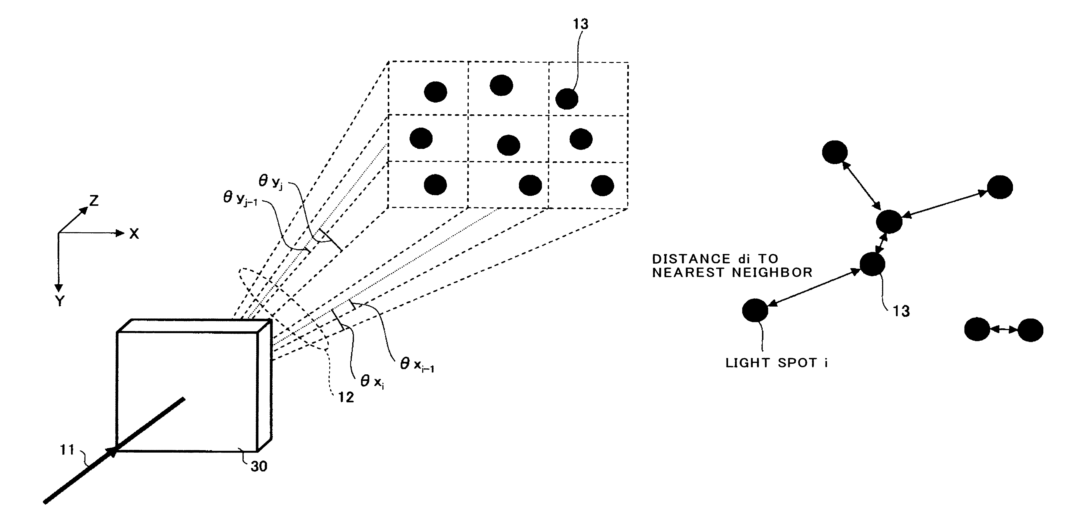
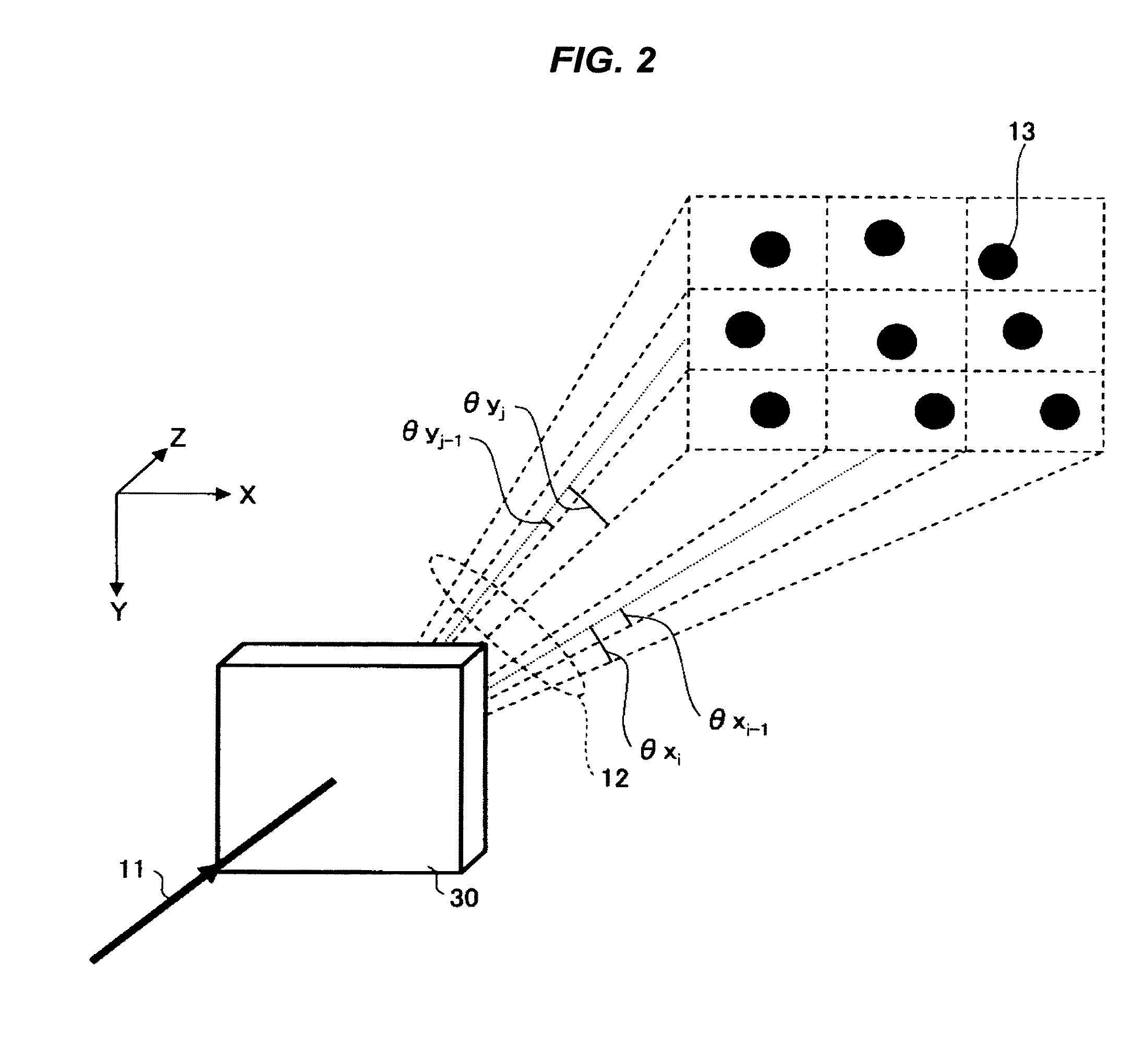
[0094]Example 1 is described below with reference to FIGS. 11A, 11B and 12. FIG. 11A shows a situation that a pattern consisting of 2500 light spots of dispersive type is generated by the diffractive optical element according to the present embodiment. In FIG. 11A, the diffractive optical element according to Example 1 is formed such that predetermined diffraction ranges are divided into 50×50 and that one light spot enters into each grid. In particular, the formation is such that each grid is divided into sub-grids of 5×5 and then one light spot is located at random at one of the sub-grids.
[0095]Then, when the above-mentioned pattern is applied to the diffracted light of −125th to 124th orders in the X-direction and −125th to 124th orders in the Y-direction and then the phase distribution of the basic unit on the diffractive optical element plane is calculated by iterative Fourier transformation, the diagram shown in FIG. 12 is obtained. In this phase distribution, eight phase valu...
example 2
[0098]Next, Example 2 is described below with reference to FIGS. 13A, 13B and 14. FIG. 13A shows a situation that a pattern consisting of 30000 light spots of dispersive type is generated by the diffractive optical element according to the present embodiment. In FIG. 13A, the diffractive optical element according to Example 2 is formed such that predetermined diffraction ranges are divided into 200×150 and that one light spot enters into each grid. In particular, the formation is such that each grid is divided into sub-grids of 3×3 and then one light spot is located at random at one of the sub-grids.
[0099]Then, when the above-mentioned pattern is applied to the diffracted light of −300th to 299th orders in the X-direction and −225th to 224th orders in the Y-direction and then the phase distribution of the basic unit on the diffractive optical element plane is calculated by iterative Fourier transformation, the diagram shown in FIG. 14 is obtained. In this phase distribution, eight p...
example 3
[0102]Next, Example 3 is described below with reference to FIGS. 15A, 15B and 16. FIG. 15A shows a situation that a pattern consisting of 30000 light spots of dispersive type is generated by the diffractive optical element according to the present embodiment. In FIG. 15A, the diffractive optical element according to Example 3 is formed such that predetermined diffraction ranges are divided into 100×75 and that four light spots enter into each grid. In particular, the formation is such that each grid is divided into sub-grids of 6×6 and then four light spots are located at random at the sub-grids.
[0103]Then, when the above-mentioned pattern is applied to the diffracted light of −300th to 299th orders in the X-direction and −225th to 224th orders in the Y-direction and then the phase distribution of the basic unit on the diffractive optical element plane is calculated by iterative Fourier transformation, the diagram shown in FIG. 16 is obtained. In this phase distribution, eight phase...
PUM
| Property | Measurement | Unit |
|---|---|---|
| angle | aaaaa | aaaaa |
| height | aaaaa | aaaaa |
| height | aaaaa | aaaaa |
Abstract
Description
Claims
Application Information
 - R&D
- Intellectual Property
- Life Sciences
- Materials
- Tech Scout
- Unparalleled Data Quality
- Higher Quality Content
- 60% Fewer Hallucinations
Browse by: Latest US Patents, China's latest patents, Technical Efficacy Thesaurus, Application Domain, Technology Topic, Popular Technical Reports.
© 2025 PatSnap. All rights reserved.Legal|Privacy policy|Modern Slavery Act Transparency Statement|Sitemap|About US| Contact US: help@patsnap.com


