Intervertebral implant devices and methods for insertion thereof

a technology of intervertebral implants and hook devices, which is applied in the field of spinal stabilization systems, can solve the problems of not allowing for variable distraction of laminar surfaces from each other, and achieve the effects of convenient assembly of hook devices, advantageous engagement, and convenient removal

Inactive Publication Date: 2013-12-10
PIONEER SURGICAL TECH INC
View PDF14 Cites 9 Cited by
  • Summary
  • Abstract
  • Description
  • Claims
  • Application Information

AI Technical Summary

Benefits of technology

[0009]In accordance with one aspect of the invention, a spinal implant assembly is provided which allows for in situ manipulation of an implant device to adjust for the geometries of the vertebral surfaces to be engaged by the implant device. The spinal implant assembly includes an upper hook portion and a lower hook portion each having seat portions configured to engage facing surfaces of adjacent vertebral bodies. An elongate guide device extends between and connects the hook portions. In one form, a multi-axial pivot connection between one of the hook portions and the elongate guide device allows the seat portions to be oriented to securely engage the vertebral surfaces despite variations in their relative positions, such as in different locations along the spine or in different patients. A slide connection between the other hook portion and the elongate guide device allows the adjacent vertebrae to be distracted with the seats securely engaged against the vertebral surfaces.
[0012]The configuration of prior art laminar distraction assemblies either allowed for the laminar surfaces to be distracted to various distances from each other while having the guide device for this purpose arranged outside the intervertebral space or axially extending envelope between the laminae of the adjacent vertebrae or substantially maintained the structure of the assembly within the laminar envelope but did not allow for variable distraction of the laminar surfaces from each other. By contrast, the above described spinal implant assembly has the hook and guide devices thereof configured and arranged to provide both a compact configuration for substantially fitting in within the laminar envelope while also allow for variable distraction of the laminar surfaces from each other.
[0013]In accordance with another aspect of the invention, a spinal implant assembly is provided which includes a releasable connection which allows for easy removal and replacement of a hook device. In this regard, the spinal implant assembly includes a pair of hook devices connected to an elongate guide device. A releasable connection between one of the hook devices and the elongate guide device allows the one hook device to be pulled off the elongate guide device for removal therefrom and to be pushed onto the elongate guide device to connect the one hook device onto the elongate guide device. In one form, the releasable connection is a snap-fit connection between the one hook device and the elongate guide device. The releasable connection advantageously allows a surgeon to easily assemble the hook device on the elongate guide device or select between different sizes of the hook device for placement on the elongate guide device. With the snap-fit connection, the use of tools is completely avoided for this purpose.
[0014]In accordance with another aspect of the invention, a method of implanting a spinal device is provided that allows for engaging and distracting adjacent vertebral bodies without requiring the adjacent vertebral bodies to be distracted prior to engagement. In this regard, the method includes positioning an implant device so that hook members of the implant device engage adjacent vertebral bodies. One of the hook members can then be pivoted about a guide portion of the implant device so that a seat portion of the one hook member is shifted into engagement with the vertebral body engaged by the one hook member. With the one hook member seat engaged with the vertebral body, the other hook member can then be translated along the guide portion away from the one hook member to distract the adjacent vertebral bodies. In one form, the method includes shifting the other hook member as the one hook member is pivoted so that the other hook member seat portion engages the vertebral body. The method advantageously allows a surgeon to insert hook members of an implant device into engagement with vertebral bodies, to then pivot one of the hook members so that the seat portions of the hook members are in engagement with the vertebral bodies, and then to distract the vertebral bodies without having to pre-distract the vertebral bodies to fit the hook members therebetween. In addition, shifting the other hook member during pivoting of the one hook member allows a surgeon to orient the seat portions to engage both vertebral bodies at one time instead of having to position each hook member individually for this purpose.
[0015]In another form, pivoting the one hook member includes pivoting the one hook member about multiple axes to adjust the orientation of the seats of the hook members to the geometry of the vertebral bodies engaged thereby. With multi-axial pivoting the one hook member to adjust for vertebral surface geometries, the implant device can advantageously engage the adjacent vertebrae more securely despite variations in their structures along the spine and between different patients.

Problems solved by technology

The configuration of prior art laminar distraction assemblies either allowed for the laminar surfaces to be distracted to various distances from each other while having the guide device for this purpose arranged outside the intervertebral space or axially extending envelope between the laminae of the adjacent vertebrae or substantially maintained the structure of the assembly within the laminar envelope but did not allow for variable distraction of the laminar surfaces from each other.

Method used


Image

  • Intervertebral implant devices and methods for insertion thereof
  • Intervertebral implant devices and methods for insertion thereof
  • Intervertebral implant devices and methods for insertion thereof

Examples


Embodiment Construction

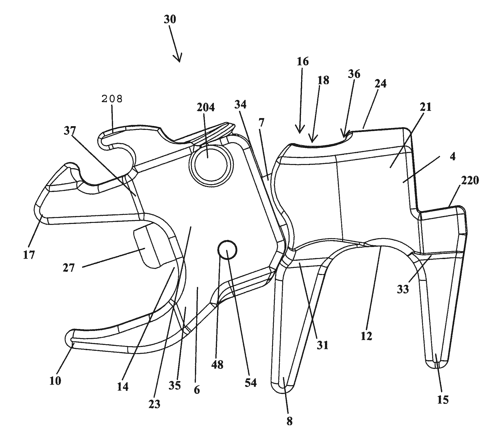
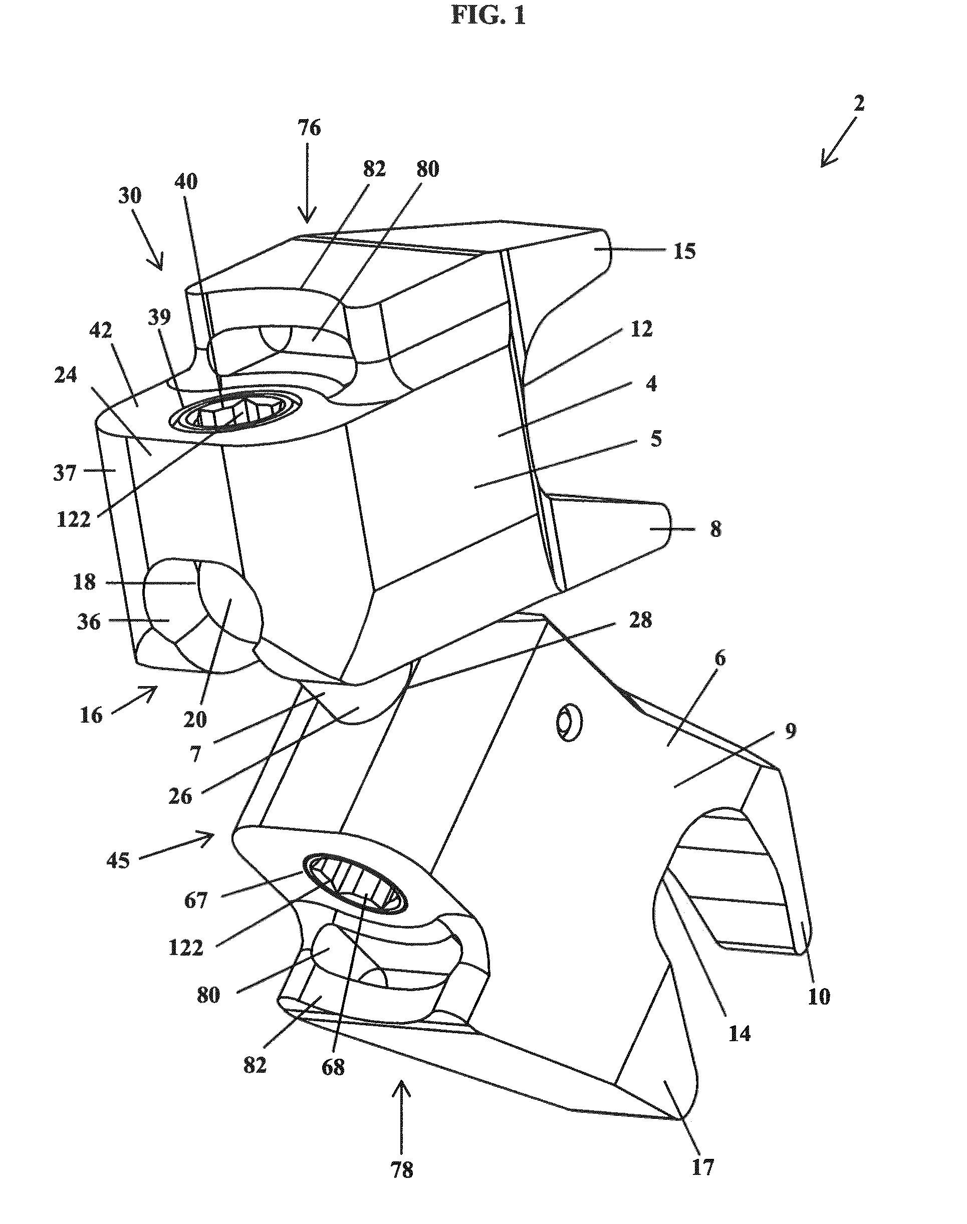
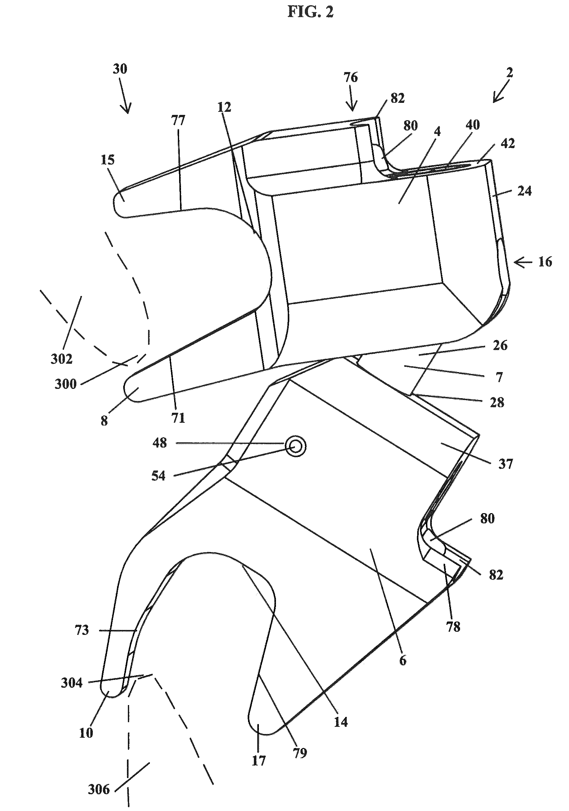
[0050]In FIGS. 1-11 and 25-30, a spinal implant device or assembly 2 is shown for being implanted between and variably distracting adjacent vertebral bodies of the human spine, and more specifically the laminae of the adjacent upper and lower vertebrae. The implant device 2 includes an upper or superior hook portion or device 1 for engaging a lower surface 300 of a superior lamina 302, a lower or inferior hook portion or device 3 for engaging an upper surface 304 of an inferior lamina 306, and an elongate guide portion or device 7 connected to each of the upper hook device 1 and the lower hook device 3, as shown in FIGS. 2, 4 and 6. The superior and inferior hook devices 4 and 6 are adjustable relative to the elongate guide device 7 and to each other so that the implant device 2 can be securely engaged between the adjacent upper and lower lamina 302 and 306 substantially irrespective of their geometries relative to each other.

[0051]As shown in FIGS. 1-4 and 25-29, the upper and lowe...


PUM


Abstract

An implant device includes a pair of hook devices and an elongate guide device. The hook devices are configured to be disposed between and engage adjacent vertebral bodies. The elongate guide device is connected to the hook devices and allows for relative movement of at least one of the hook devices to adjust for the geometries of the vertebral surfaces to be engaged by the hook devices.

Description

CROSS REFERENCE TO RELATED APPLICATIONS[0001]This application claims the benefit of U.S. Provisional Application No. 61 / 260,551, filed Nov. 12, 2009, and is a continuation-in-part of U.S. patent application Ser. No. 12 / 234,557, filed Sep. 19, 2008, now U.S. Pat. No. 8,308,767, and claims the benefit of the filing date of U.S. Provisional Application No. 60 / 973,659, filed Sep. 19, 2007, all of which are hereby incorporated by reference in their entirety herein.FIELD OF THE INVENTION[0002]The present invention relates generally to a spinal stabilization system and, more particularly, a spinal stabilization system for distracting and limiting reduction of the intervertebral spacing between adjacent vertebrae.BACKGROUND[0003]This invention pertains to medical implantable devices and particularly to spinal implants. Various devices for internal fixation of bone segments in the human or animal body are known in the art. The most common types of spinal implant systems are hook and rod syst...

Claims


Application Information

Patent Timeline
Patent Type & Authority Patents(United States)
IPC IPC(8): A61B17/70
CPCA61B17/7065A61B17/7068
Inventor HOCHSCHULER, STEPHEN H.ARAGHI, ALIKILPELA, THOMAS S.HOFFMAN, JEFFREY A.JACKSON, MICHAEL R.PIETILA, RUSSELL M.
Owner PIONEER SURGICAL TECH INC
Why Eureka
Try Eureka