Spatial light modulator with masking-comparators

a technology of spatial light modulator and masking, applied in the field of digital backplane, can solve the problems of limited brightness and power efficiency, and the brightness of the projector with a given light source is also limited

Active Publication Date: 2013-12-10
SYNDIANT
View PDF16 Cites 388 Cited by
  • Summary
  • Abstract
  • Description
  • Claims
  • Application Information

AI Technical Summary

Problems solved by technology

Display systems using microdisplay spatial light modulators (SLM) with solid-state illumination such as LEDs and lasers are used in many products today, but they have limitations in brightness and power efficiency.
The brightness of the projectors with a given light source is also limited by the total amount of light-on time (time that the light sources can be turned on) that the SLMs allow.

Method used


Image

  • Spatial light modulator with masking-comparators
  • Spatial light modulator with masking-comparators
  • Spatial light modulator with masking-comparators

Examples


Embodiment Construction

[0032]It is advantageous to define several terms before describing the invention. It should be appreciated that the following definitions are used throughout this application.

Definitions

[0033]Where the definition of terms departs from the commonly used meaning of the term, applicant intends to utilize the definitions provided below, unless specifically indicated.

[0034]For purposes of the present invention, it should be noted that the singular forms, “a”, “an”, and “the” include reference to the plural unless the context as herein presented clearly indicates otherwise.

[0035]For purposes of the present invention, directional terms such as “top”, “bottom”, “upper”, “lower”, “above”, “below”, “left”, “right”, “horizontal”, “vertical”, “up”, “down”, etc. are merely used for convenience in describing the various embodiments of the present invention. The embodiments of the present invention may be oriented in various ways. For example, the diagrams, apparatuses, etc. shown in the drawing f...


PUM


Abstract

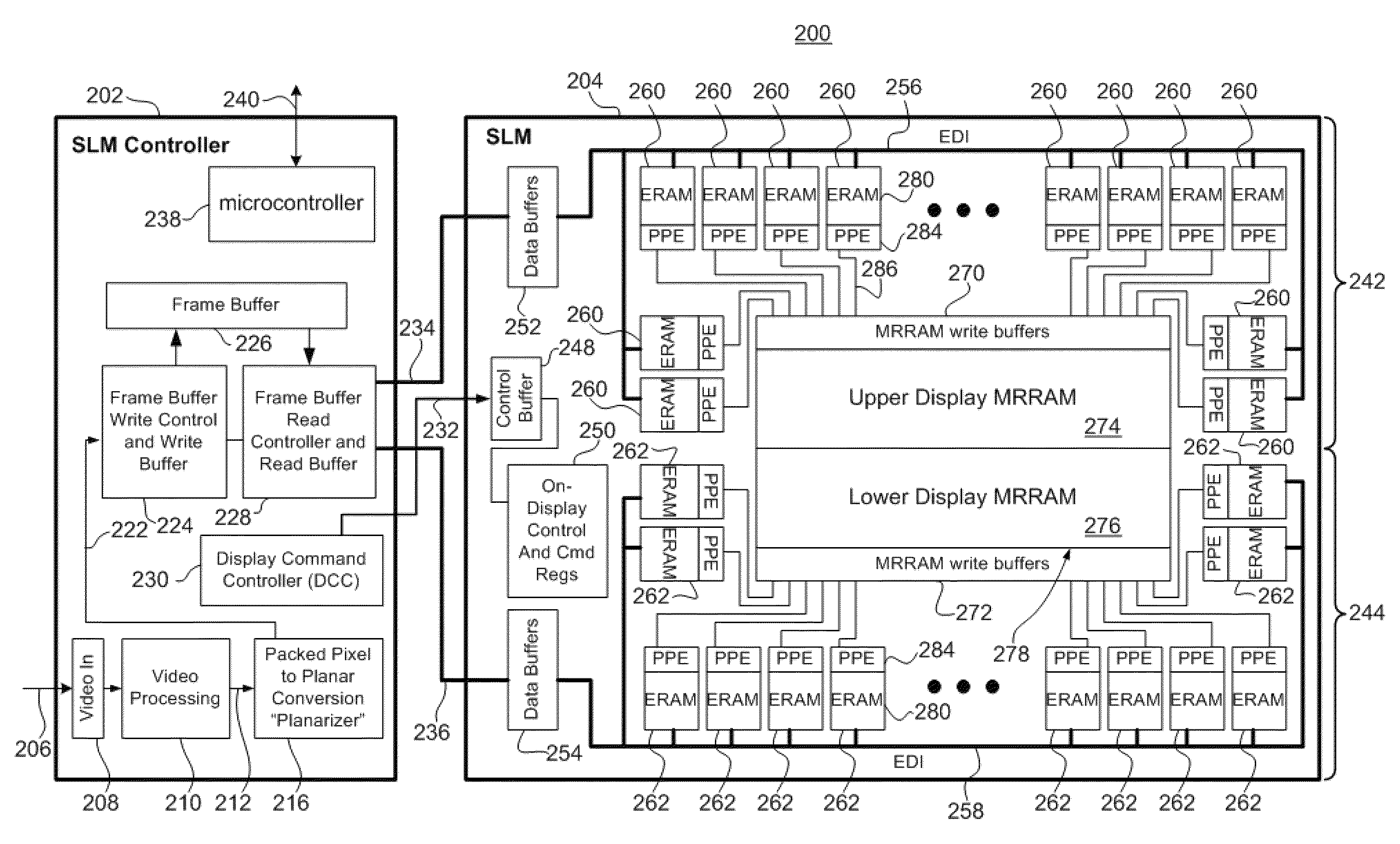
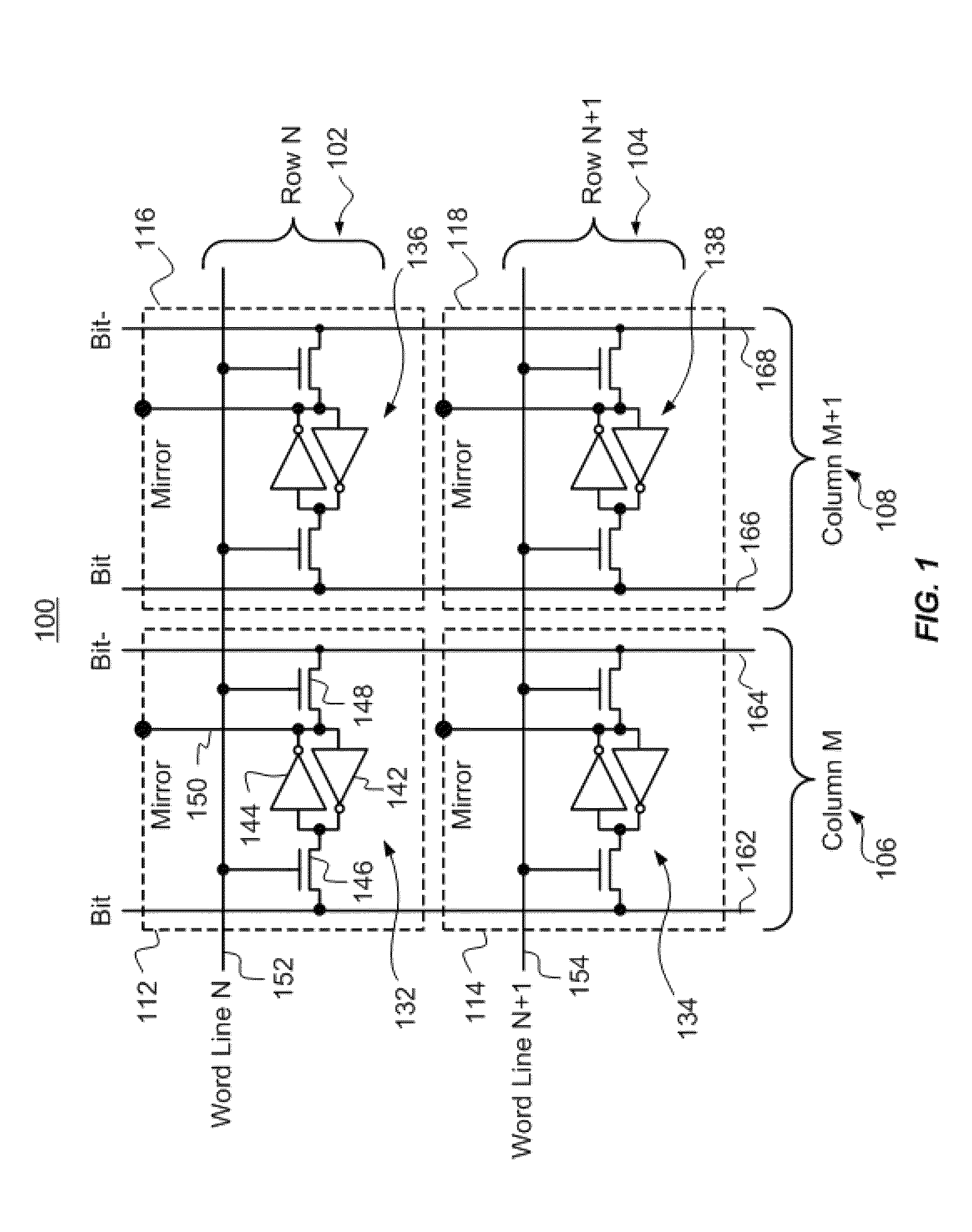
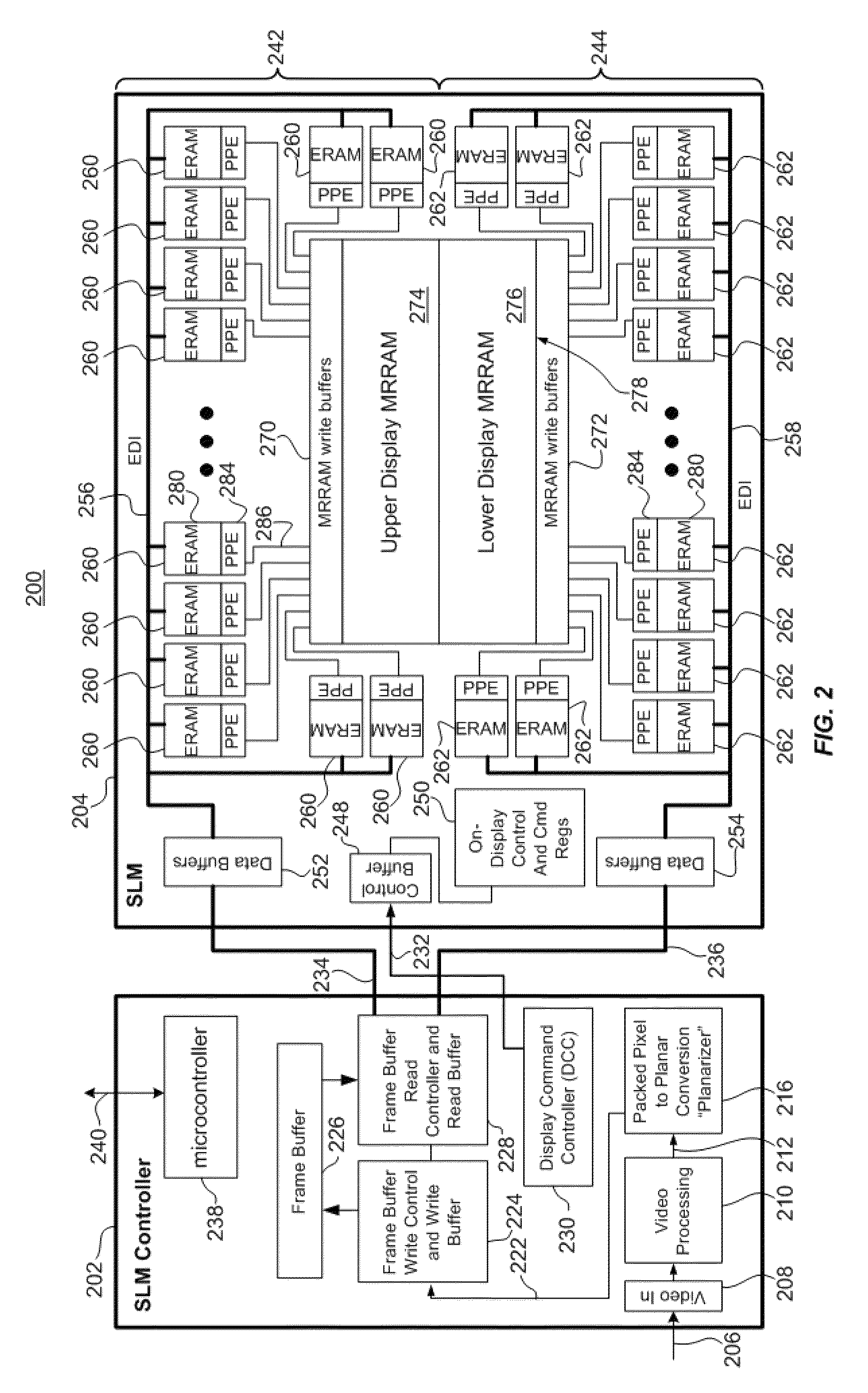
Described is a device comprising a spatial light modulator comprising a plurality of comparators for computing a respective drive for each pixel of a plurality of pixels.

Description

CROSS-REFERENCE TO RELATED APPLICATIONS[0001]This application claims benefit of priority to U.S. Provisional Patent Application No. 61 / 289,522 to Guttag et al., entitled “SPATIAL LIGHT MODULATOR WITH CONDITIONAL PARALLEL PROCESSING,” filed Dec. 23, 2009, which is incorporated herein by reference in its entirety.BACKGROUND[0002]1. Field of the Invention[0003]The present invention relates to digital backplanes and various methods, systems and devices for controlling a digital backplane, light modulating elements and spatial light modulators.[0004]2. Related Art[0005]Display systems using microdisplay spatial light modulators (SLM) with solid-state illumination such as LEDs and lasers are used in many products today, but they have limitations in brightness and power efficiency. The brightness of the projectors with a given light source is also limited by the total amount of light-on time (time that the light sources can be turned on) that the SLMs allow.SUMMARY[0006]According to a firs...

Claims


Application Information

Patent Timeline
Patent Type & Authority Patents(United States)
IPC IPC(8): G09G3/34
CPCG09G3/3685G09G3/2014G06T1/20G09G5/10G09G2310/0235G09G2310/061
Inventor GUTTAG, KARL MARIONWALLER, CRAIG MICHAELLUND, JOSHUA ABRAHAMRUSSELL, ANDREW IAN
Owner SYNDIANT
Why Eureka
Try Eureka