System and method for calibrating a spatial light modulator

a spatial light modulator and light source technology, applied in the field of calibration of spatial light modulators, can solve the problems of prohibitive calibration time, unsatisfactory viewing of one pixel at a time by turning off all other pixels,

Inactive Publication Date: 2005-08-04
ASML HLDG NV
View PDF33 Cites 120 Cited by
  • Summary
  • Abstract
  • Description
  • Claims
  • Application Information

AI Technical Summary

Problems solved by technology

However, viewing one pixel at a time by turning off all other pixels is not desirable because the calibration time becomes prohibitive.
The problem of such an approach ...

Method used


Image

  • System and method for calibrating a spatial light modulator
  • System and method for calibrating a spatial light modulator
  • System and method for calibrating a spatial light modulator

Examples


Embodiment Construction

Overview

[0027] While specific configurations and arrangements are discussed, it should be understood that this is done for illustrative purposes only. A person skilled in the pertinent art will recognize that other configurations and arrangements can be used without departing from the spirit and scope of the present invention. It will be apparent to a person skilled in the pertinent art that this invention can also be employed in a variety of other applications.

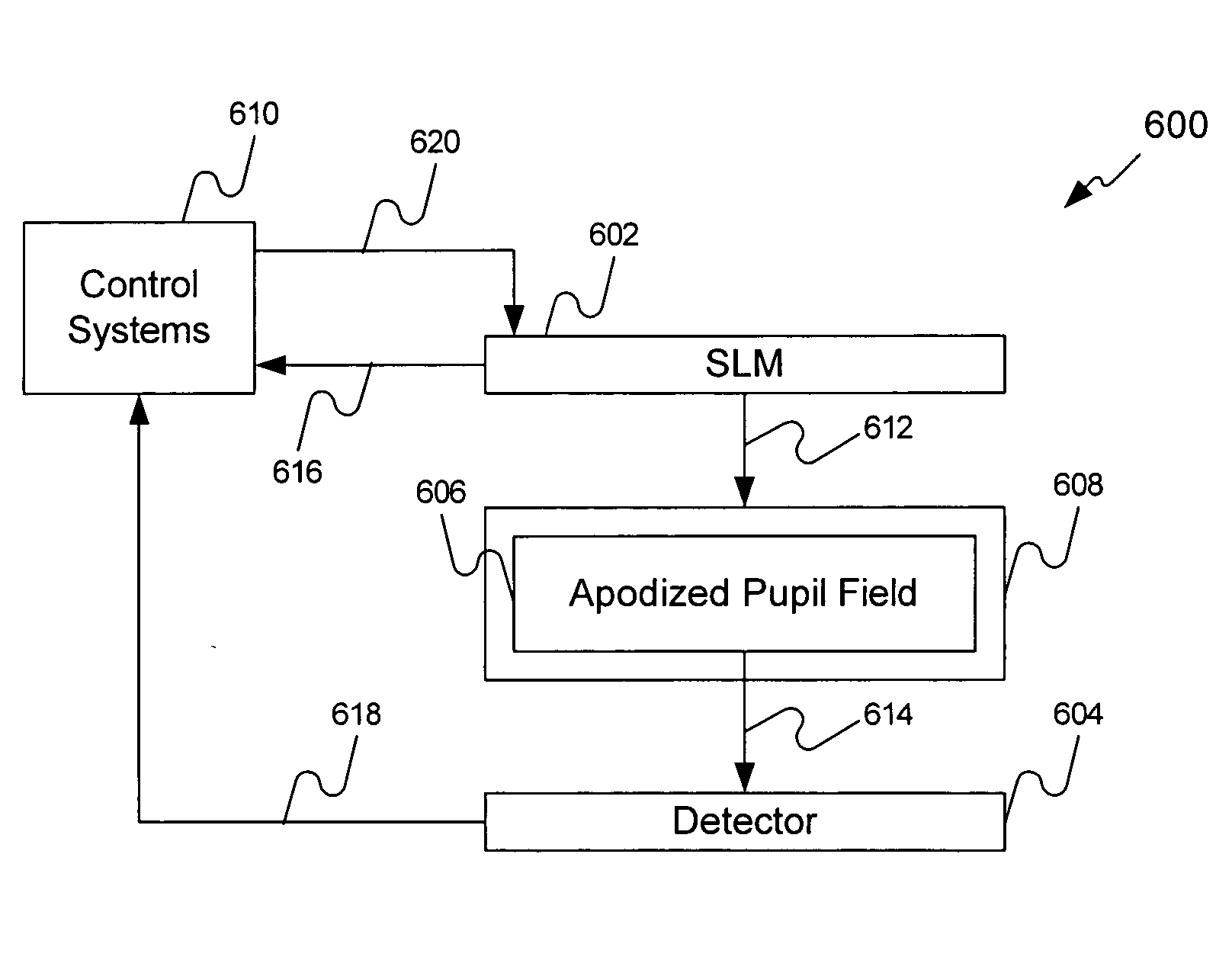
[0028] Embodiments of the present invention provide a method and system including a reflective SLM having an array of pixels (e.g., mirrors) and a projection optical system having an apodized pupil. During a calibration operation, the mirrors of the SLM receive varying voltage values to either continuously or incrementally move (e.g:, movement can be to tilt, pivot, rotate, etc., hereinafter all are referred to as “move”) them through various angles. Light reflecting from each of the pixels during these movements forms ind...


PUM


Abstract

A method and system as used to calibrate a reflective SLM. The system can include a reflective SLM having an array of pixels (e.g., moving, tilting, rotating, pivoting, etc. pixels) and a projection optical system resolving individual pixels and having an apodized pupil. During a calibration operation, the pixels of the SLM receive varying voltage values to either continuously or incrementally move them through various angles. Light reflecting from each of the pixels during these movements forms individual images for each pixel at each angle. The light passes through the apodized pupil and is received on one or more sections (e.g., pixels) of a detector (e.g., a CCD array). The pupil apodization pattern is selected so that individual pixels remain well resolved and their resolved images have strong sensitivity to the pixel mirror tilt. The light intensity received for each pixel at each angle is correlated to the voltage value received at the pixel to tilt the pixel to that angle. The correlation produces a result signal. The result signal is used by a control device before and during normal operation of the SLM to calibrate the SLM one or more times.

Description

BACKGROUND OF THE INVENTION [0001] 1. Field of the Invention [0002] The present invention is related to calibrating spatial light modulators having reflective pixels, and more particularly to calibrating reflective spatial light modulators utilized in maskless lithography systems. [0003] 2. Background Art [0004] Spatial light modulators (SLMs) (e.g., digital mirror devices (DMDs), liquid crystal displays (LCDs), grating light valves (GLVs), or the like) are used in many different environments to pattern objects or project patterns, for example, lithography (e.g., maskless lithography), televisions, biomedical systems, biotechnology systems, etc. SLMs can include an active area having an n×m (wherein n and m are integers equal to or greater than 1) array of active devices (or pixels) (e.g., an array of mirrors on the DMD or GLV or an array of reflective / transmissive devices on the LCD). Each active device is individually controlled to move (e.g., tilt, rotate, pivot, etc.) the active...

Claims


Application Information

Patent Timeline
IPC IPC(8): G02B26/08G01M11/00G02B27/58G03F7/20H01L21/027
CPCG03F7/70291G02B27/58
Inventor LATYPOV, AZAT M.POULTNEY, SHERMAN K.
Owner ASML HLDG NV
Why Eureka
Try Eureka