System for the production of a dynamic image for display

a dynamic image and display technology, applied in the field of system for the production of dynamic images for display, can solve the problems of low resolution, no conventional spatial light modulators offer the potential to achieve small pixel, and none offer the number of pixels typical of latent image holograms

Inactive Publication Date: 2002-08-20
F POSZAT HU
View PDF8 Cites 122 Cited by
  • Summary
  • Abstract
  • Description
  • Claims
  • Application Information

AI Technical Summary

Benefits of technology

This enables the image produced at the second spatial light modulator means, which operates at a far slower read-out rate than the update rate of first spatial light modulator means, to be effectively governed by the operation of the first spatial light modulator means. This permits a trade off between the temporal information available in high frame-rate spatial light modulators and thereby obtain a high complexity system working at a lower frame rate. It will be apparent to those skilled in the art that the term complexity as used herein refers to the number of pixels capable of being displayed on the spatial light modulator.
The first spatial light modulator means may be electrically addressable. This enables a fast rate of dynamic pattern to be produced.
The complexity of the first spatial light modulator means may be less than the complexity of the second spatial light modulator means. This allows, for example, for repeat patterns to be formed on the second spatial light modulator means. In a preferred embodiment, the modulated light from the first spatial light modulator means may be replicated at the second spatial light modulator means by the relay optics means. Additionally the replication of the modulated light may comprise a plurality of patterns. Usefully the relay optics means guides the replicated modulated light time-sequentially to predetermined portions of the second spatial light modulator. In this way the relay optics means may reproduce a pattern at the second spatial light modulator of that provided by the first spatial light modulator.

Problems solved by technology

The above desirable result, however, meets with drawbacks because whilst conventional spatial light modulators are fabricated using a wide variety of techniques, they all suffer from an number of problems.
None of the conventional spatial light modulators offer the potential to achieve small pixel sizes which are necessary to achieve the desired field of view.
Additionally, none offer the number of pixels typically seen in a latent image hologram.
The low resolution due to the low number of pixels results simply from the limits of technology at the present time.
Even in leading systems, using a acousto-optic modulators and passive addressed ferroelectric liquid crystal modulators, the maximum number of pixels is limited by various reasons.
The acousto-optic systems are limited due to the modulation bandwidth of the acousto-optic modulator which is typically a few-several hundred MHz.
In liquid crystal systems this is due to the manufacturability of very complex displays.
This permits a trade off between the temporal information available in high frame-rate spatial light modulators and thereby obtain a high complexity system working at a lower frame rate.

Method used


Image

  • System for the production of a dynamic image for display
  • System for the production of a dynamic image for display
  • System for the production of a dynamic image for display

Examples


Embodiment Construction

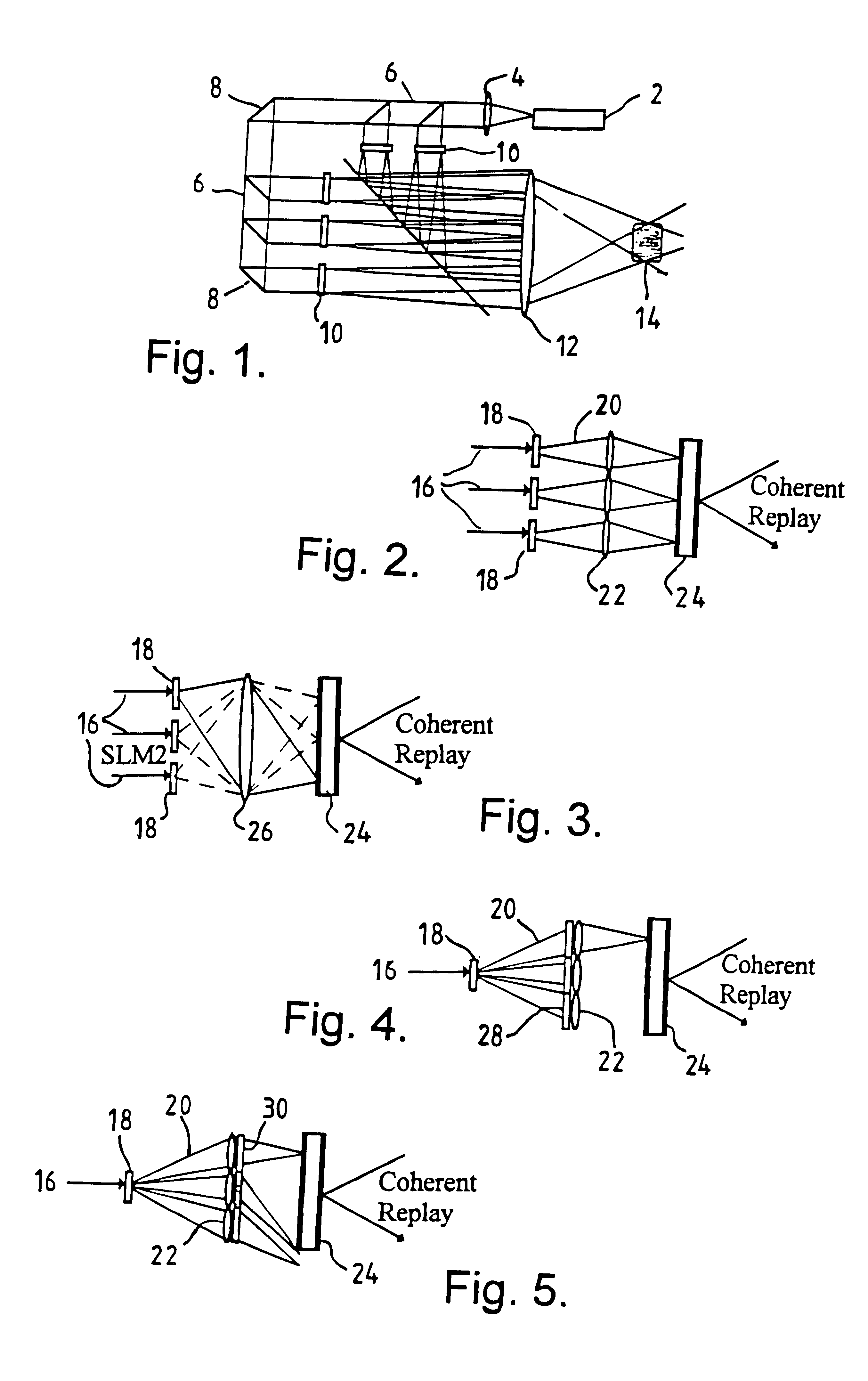
By referring first to FIG. 1 a known device for the optical recombination of light from many spatial light modulators is shown. A laser light source 2 provides a collimated beam via lens 4 through a plurality of beam splitters 6 and mirrors 8 to spatial light modulators 10 which then allow the light to pass through a final focusing lens 12 to provide a holographic image 14 in a known manner. In order for such a system to be able to replay high complexity high resolution generated holographic images, the light from the spatial light modulators (herein referred to as SLM) 10 needs to be optically recombined. Those skilled in the art will appreciate that the term "complexity" as used herein refers to the number of pixels in the SLM grid. The example shown in FIG. 1 utilises the inherent parallel nature of optical systems. Furthermore the complexity available for the generated holographic image increases in proportion to the number of SLMs used.

Referring now to FIG. 2 it can be seen tha...


PUM

PropertyMeasurementUnit
electrically addressableaaaaaaaaaa
ferroelectricaaaaaaaaaa
phaseaaaaaaaaaa

Abstract

A system for the production of a dynamic image for use in holography includes a light source (16) which travels via a liquid crystal modulator (18) placed in the path of the light source (16). The output of the LC modulator (18) passes modulated light through a lens array (22) which itself guides light to an optically addressed spatial light modulator (24). The resulting real image from the optically addressed spatial light modulator (24) may be used in holography. The addressing frame-rate of the liquid crystal modulator (18) is substantially greater than the frame-rate of the optically addressed spatial light modulator (24).

Description

1. Field of the InventionThe present invention relates to a system for the production of a dynamic image for display and has particular, although not exclusive, relevance to such systems employing liquid crystal display devices for use in holography.2. Discussion of Prior ArtIt has long been known to use holographic techniques to produce a three-dimensional image of an object which has all of the depth cues used by the human brain in its image processing. Conventionally a real three-dimensional object is used in the production of the hologram by known techniques.It is also known to use holographic stereogram techniques which, rather than rely on real three-dimensional object in the production of the hologram, rely upon multiple flat, two-dimensional, objects having different perspectives of a scene encoded as light intensity or phase differences across the surface thereof which can be used to produce a hologram therefrom.Interferometrically derived, so-called display holography requ...

Claims


Application Information

Patent Timeline
Patent Type & Authority Patents(United States)
IPC IPC(8): G02B5/32G03H1/22G03H1/00H04N5/74G02F1/01G02B27/22G02F1/1347G03H1/08G09G3/20G09G3/36
CPCG02B5/32G03H1/02G03H1/2294H04N5/74G03H2001/0224G03H2001/221G03H2001/2292G03H2001/2297G03H2001/262G03H2001/2655G03H2222/22G03H2223/19G03H2225/22G03H2225/25G03H2225/55G03H2225/60H04N5/7441G03H1/2249G03H2210/30
Inventor BROWN, CARL VSTANLEY, MAURICE
Owner F POSZAT HU
Why Eureka
Try Eureka