Personal Display Using an Off-Axis Illuminator

a technology of off-axis illumination and personal display, applied in the field of personal display using an off-axis illumination, can solve the problems of large product size, heavy weight, and high cost of many applications, and achieve the effect of increasing the number of applications, and increasing the cost of production

Inactive Publication Date: 2007-08-02
SYNOPSYS INC
View PDF15 Cites 128 Cited by
  • Summary
  • Abstract
  • Description
  • Claims
  • Application Information

AI Technical Summary

Problems solved by technology

As many components are included in the optical systems, the products become larger, heavier, and more expensive than desired for many applications.

Method used


Image

  • Personal Display Using an Off-Axis Illuminator
  • Personal Display Using an Off-Axis Illuminator
  • Personal Display Using an Off-Axis Illuminator

Examples


Embodiment Construction

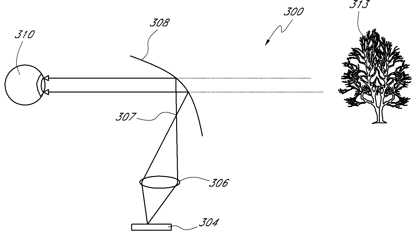
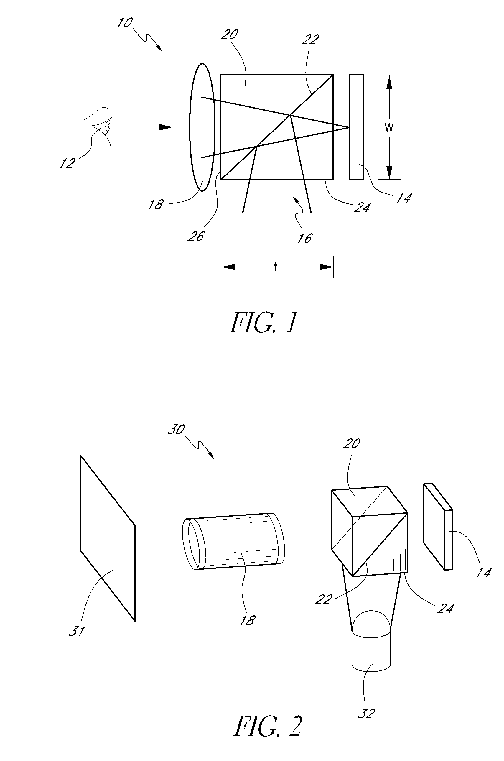
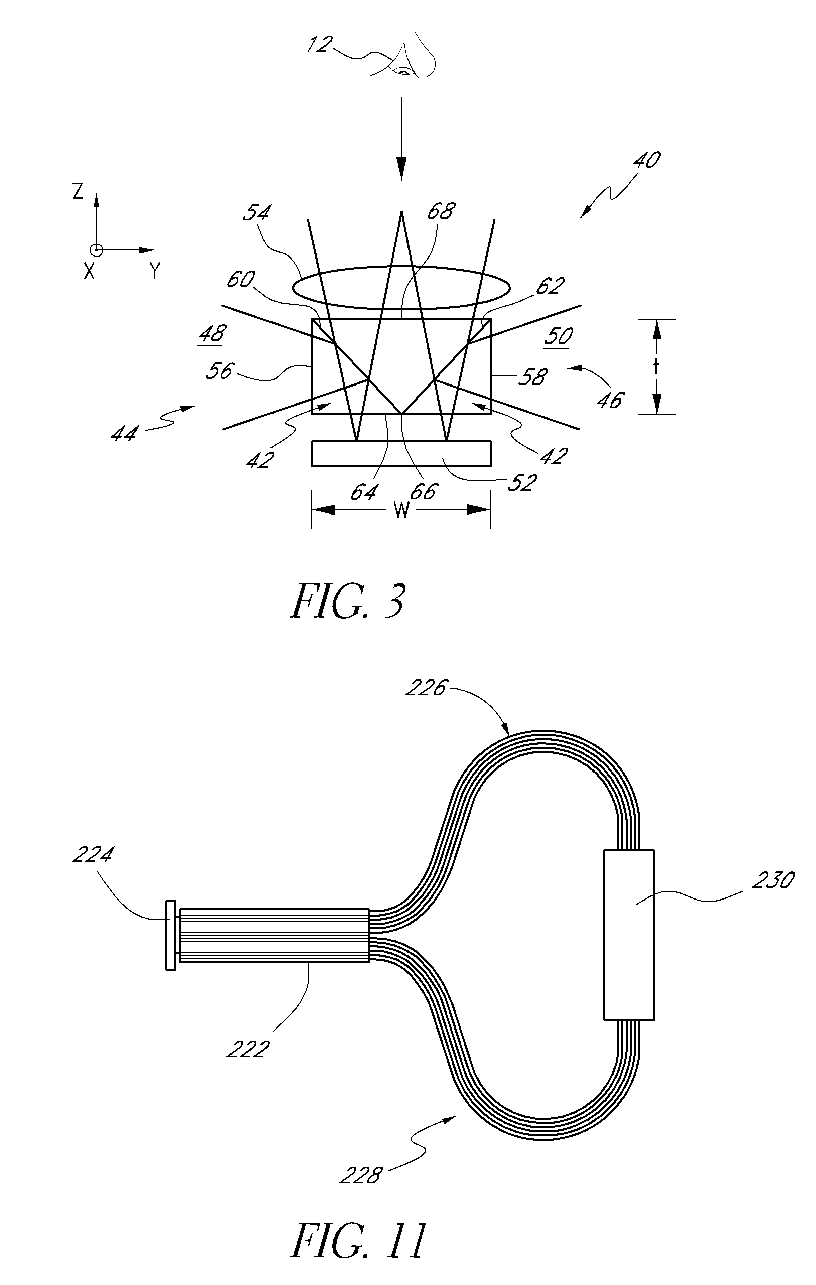
[0063] To present graphics or other visual information to a viewer, images and / or symbols, e.g., text or numbers, can be projected onto a screen or directed into the viewer's eye. FIG. 1 schematically illustrates a display 10 disposed in front of a viewer 12 (represented by an eye). In a preferred embodiment, this display 10 includes a spatial light modulator 14 that is illuminated with light 16 and imaged with imaging or projection optics 18. The spatial light modulator 14 may comprise, for example, a reflective polarization modulator such as a reflective liquid crystal display. This liquid crystal spatial light modulator preferably comprises an array of liquid crystal cells each which can be individually activated by signals, e.g., analog or digital, to produce a high resolution pattern including characters and / or images. More generally, the spatial light modulator may comprise an array of modulators or pixels that can be selectively adjusted to modulate light. The projection opti...


PUM

PropertyMeasurementUnit
anglesaaaaaaaaaa
anglesaaaaaaaaaa
anglesaaaaaaaaaa

Abstract

Certain embodiments include a head mounted display for displaying images that can be viewed by a wearer when the display is worn on the wearer's head. The display can include a spatial light modulator having an array of pixels selectively adjustable for producing spatial patterns. The array of pixels can define a substantially planar reflective surface on the spatial light modulator. The display can further include a light source. The display can also include illumination optics disposed to receive light from the light source and direct light onto the planar reflective surface of the spatial light modulator at an angle with respect to the surface normal of the planar reflective surface. The display can include imaging optics disposed with respect to the spatial light modulator to receive light from the spatial light modulator. The display can further include a curved reflector disposed to reflect light from the imaging optics so as to form a virtual image such that the image may be viewed by an eye of the wearer. The display can also include headgear for supporting the spatial light modulator, imaging optics, and reflector. In certain embodiments, only rays of light incident on the planar reflective surface of the spatial light modulator at an angle with respect to the surface normal of the planar reflective surface contribute to the virtual image viewable by the eye.

Description

RELATED APPLICATIONS [0001] This application claims the benefit under 35 U.S.C. § 119(e) of U.S. Provisional Application No. 60 / 755,974, filed Jan. 4, 2006, entitled PERSONAL DISPLAY USING AN OFF-AXIS ILLUMINATOR (Attorney Docket No. OPTRES.066PR), the entire contents of which are hereby incorporated by reference herein and made a part of this specification. [0002] This application also incorporates by reference herein each of the following applications in its entirety: U.S. patent application Ser. No. 10 / 852,728, filed May 24, 2004, entitled BEAMSPLITTING STRUCTURES AND METHODS IN OPTICAL SYSTEMS (Attorney Docket No. OPTRES.022A1); U.S. patent application Ser. No. 10 / 852,679, filed May 24, 2004, entitled APPARATUS AND METHODS FOR ILLUMINATING OPTICAL SYSTEMS (Attorney Docket No. OPTRES.022A2); U.S. patent application Ser. No. 10 / 852,669, filed May 24, 2004, entitled LIGHT DISTRIBUTION APPARATUS AND METHODS FOR ILLUMINATING OPTICAL SYSTEMS (Attorney Docket No. OPTRES.022A3); U.S. pa...

Claims


Application Information

Patent Timeline
Patent Type & Authority Applications(United States)
IPC IPC(8): G02B27/14G02F1/1335
CPCG02B5/04G02B13/22G02B17/08G02B17/0892G02B27/0172G02B2027/0178G02B27/1066G02B27/144G02B27/145G02B27/149G02B27/283G02B27/1033
Inventor MCGUIRE, JAMES JR.
Owner SYNOPSYS INC
Why Eureka
Try Eureka