Mounting an AGB on an intermediate casing for a turbojet fan compartment

a technology for turbojet fans and intermediate casings, which is applied in the direction of machines/engines, sustainable transportation, mechanical apparatus, etc., can solve the problems of difficult to form flanges, rise to aerodynamic impacts that are very penalizing, and technical difficulties

Active Publication Date: 2013-12-17
SN DETUDE & DE CONSTR DE MOTEURS DAVIATION S N E C M A
View PDF7 Cites 4 Cited by
  • Summary
  • Abstract
  • Description
  • Claims
  • Application Information

AI Technical Summary

Benefits of technology

[0007]The main aim of the present invention is therefore to overcome such drawbacks by providing a way of mounting an AGB in the core compartment of the turbojet without degrading the performance of the high-pressure compressor of the turbojet.
[0013]The intermediate casing of a turbojet is positioned between the low-pressure compressor and the high-pressure compressor. Also, the AGB that is suspended from a beam fastened on the cheek plate of the intermediate casing may be arranged around the high-pressure compressor of the turbojet without being directly fastened thereto. Any risk of reducing the performance of the casing of the high-pressure compressor by ovalization is thus removed. In addition, mounting the AGB in accordance with the invention makes it possible to move the AGB away from the cheek plate of the intermediate casing in such a manner as to be able to leave a space for passing air tubes for discharging air upstream from the high-pressure compressor.
[0014]In an advantageous arrangement, the AGB is fastened at one end to the beam and at its opposite end to a yoke that is fastened to the cheek plate, the casing further comprising a fuel unit fastened at one end to the yoke of the cheek plate and at its opposite end to the beam. The addition of the fuel unit thus makes it possible to form with the AGB, a full circle centered on the longitudinal axis of the turbojet, which facilitates balancing weights in optimum manner about said longitudinal axis. In addition, each AGB may be removed independently of the others, and that facilitates maintenance thereof.

Problems solved by technology

Unfortunately, it is not easy to form flanges enabling an AGB to be attached on such casings made of composite material.
Said enlargement nevertheless gives rise to aerodynamic impacts that are very penalizing in terms of performance.
However, that type of mounting leads to technical difficulties.
In particular, installing a considerable load on the casing of the high-pressure compressor risks reducing the performance of said casing because of a phenomenon of ovalization of the casing (ovalization has a correspondingly greater effect when the diameter of the compressor casing is small).
Furthermore, the presence of air tubes for discharging air upstream from the high-pressure compressor during some stages of flight limits the possibilities of attaching the AGB on components of the core compartment, other than on the casing of the high-pressure compressor.

Method used


Image

  • Mounting an AGB on an intermediate casing for a turbojet fan compartment
  • Mounting an AGB on an intermediate casing for a turbojet fan compartment
  • Mounting an AGB on an intermediate casing for a turbojet fan compartment

Examples


Embodiment Construction

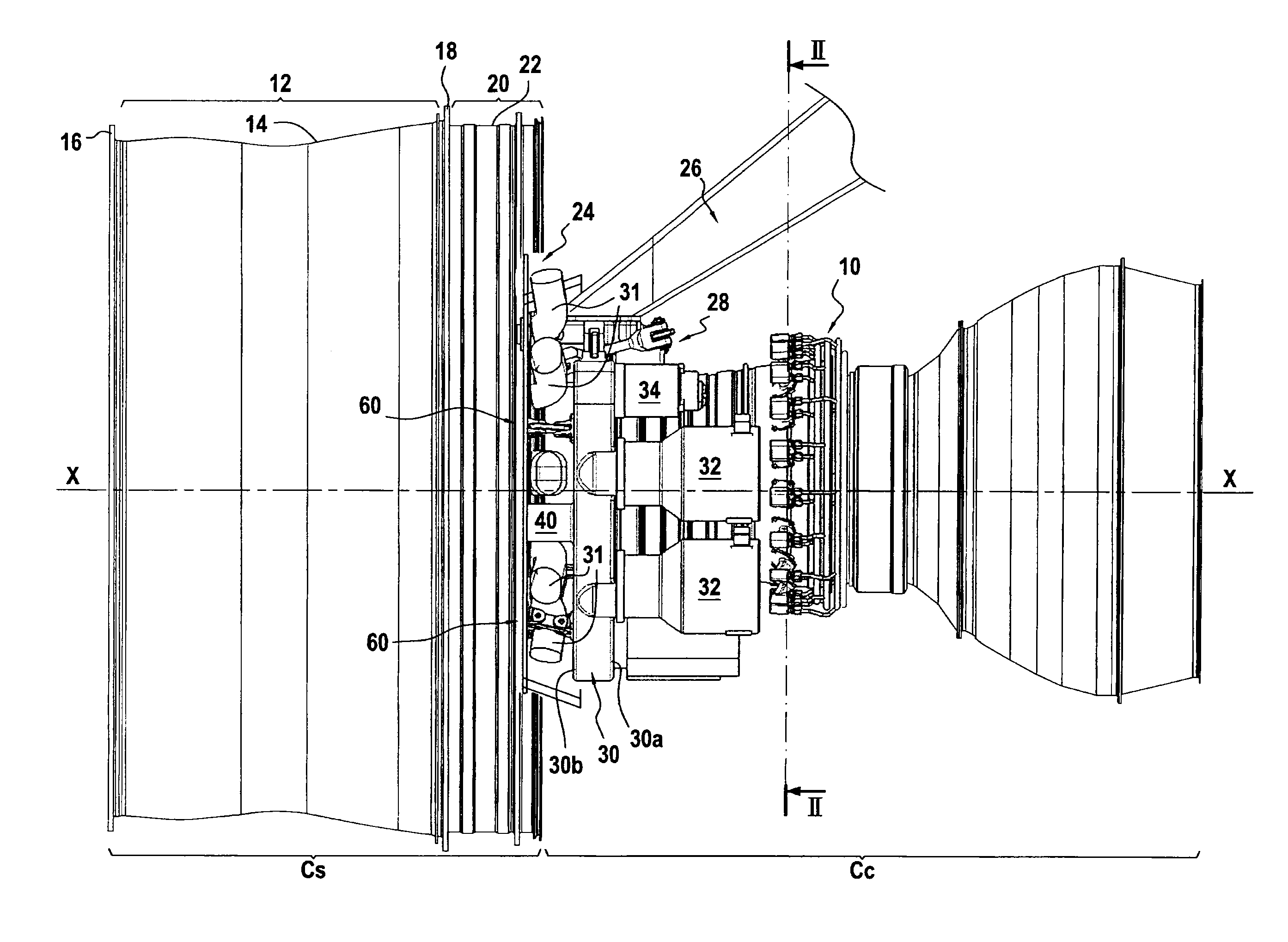
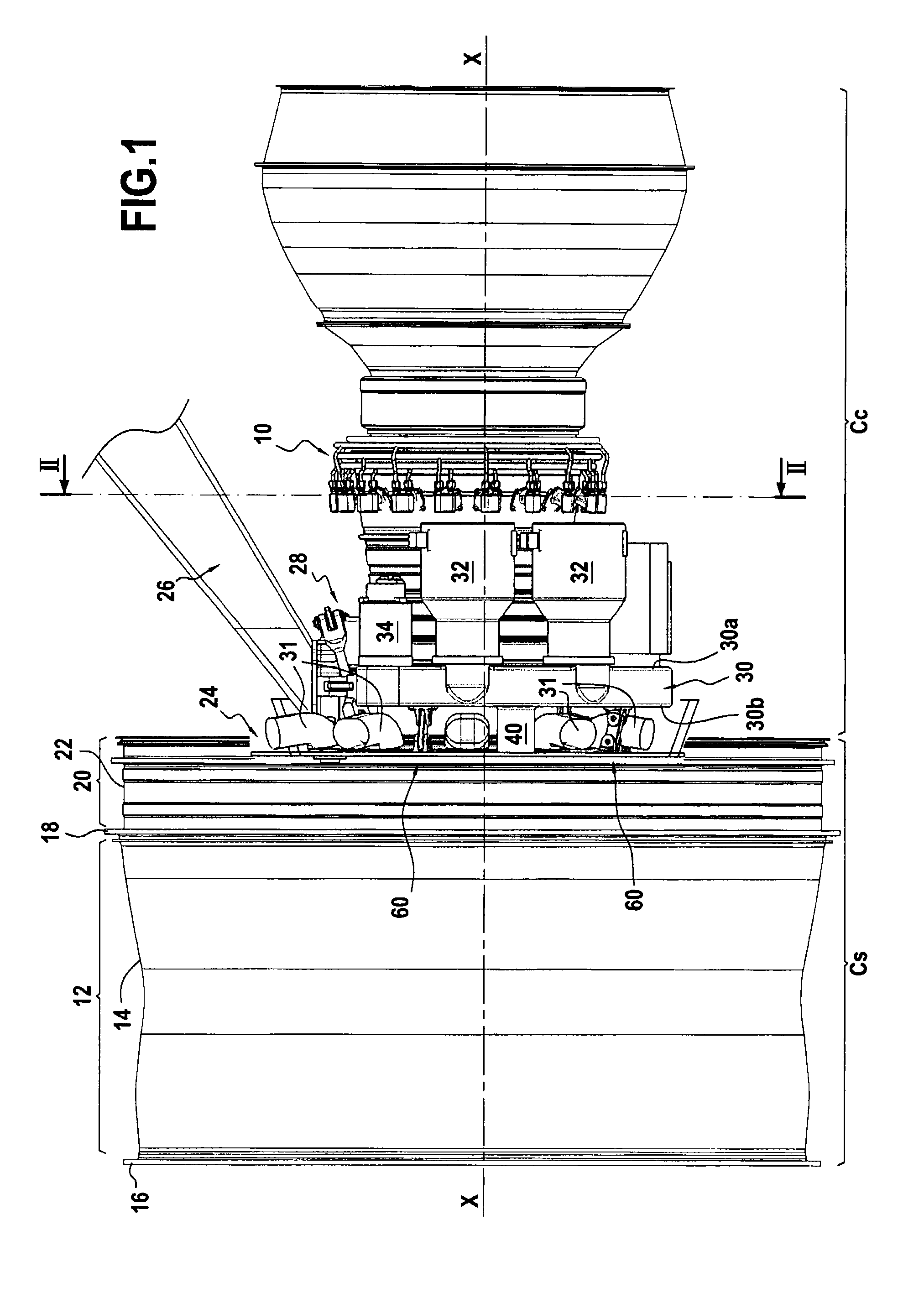
[0024]FIG. 1 is a side view showing a turbojet 10 of the two-spool bypass turbojet type, fitted with an intermediate casing of the invention. Naturally, the field of application of the invention extends to other types of turbojet.

[0025]In known manner, such a turbojet 10 is made up of an upstream compartment in which the fan is housed, also called the fan compartment CS, and a downstream compartment in which the remainder of the turbojet is housed, also called the “core” CC, or central compartment.

[0026]More precisely, the fan compartment CS includes a blade-containment casing 12 that is made up of a shroud 14 (preferentially made out of composite material) centered on the longitudinal axis X-X of the turbojet and provided at both of its ends with flanges, namely an upstream flange 16 and a downstream flange 18.

[0027]The fan compartment also includes an intermediate casing 20 fastened to the downstream flange 18 of the containment casing 12. Said intermediate casing is made up of a ...


PUM


Abstract

An intermediate casing for a turbojet fan compartment, including: a shroud centered along a longitudinal axis of the turbine engine; an annular cheek plate centered along the longitudinal axis of the turbine engine and mounted against a downstream face of the shroud; a suspension beam fastened to the cheek plate and extending downstream parallel to the longitudinal axis of the turbine engine; and an AGB suspended from the beam and including an upstream side face spaced apart axially from the cheek plate, a downstream side face opposite the upstream side face, and a plurality of accessories mounted against its downstream side face and distributed about the longitudinal axis of the turbine engine.

Description

BACKGROUND OF THE INVENTION[0001]The present invention relates to the general field of mounting an accessory driver unit on a turbojet.[0002]In a turbojet, the accessories, such as the pumps for producing hydraulic energy, feeding fuel, and providing lubrication, and also the electricity generators for producing electrical power, etc. are grouped together within a unit commonly referred to as an accessory gearbox (AGB). Such a unit generally comprises one or more gear trains that are driven in rotation by power taken from a shaft of the turbojet and that are coupled to the various accessories.[0003]In turbojets of the CFM® family, the AGBs are generally mounted in the zone or region of the fan compartment. More precisely, they are suspended from flanges formed on the metal blade-containment casing of said fan compartment.[0004]However, the containment casings of fan compartments are being made more and more frequently out of a composite material in an attempt to save weight. Unfortu...

Claims


Application Information

Patent Timeline
Patent Type & Authority Patents(United States)
IPC IPC(8): F02C9/20
CPCF02C7/32Y02T50/672Y02T50/60
Inventor FERT, JEREMY EDMOND
Owner SN DETUDE & DE CONSTR DE MOTEURS DAVIATION S N E C M A
Why Eureka
Try Eureka