Fuel cell system

a fuel cell and system technology, applied in the field of fuel cell systems, can solve the problems of lowering the precision of pressure adjustment and the responsiveness to pressure, and achieve the effect of satisfying the responsiveness

Active Publication Date: 2013-12-17
TOYOTA JIDOSHA KK
View PDF24 Cites 0 Cited by
  • Summary
  • Abstract
  • Description
  • Claims
  • Application Information

AI Technical Summary

Benefits of technology

[0006]The present invention has been developed in view of such a situation, and an object thereof is to appropriately change the supply pressure of a fuel gas in accordance with the operation state of a fuel cell and to secure a satisfactory responsiveness to pressure while minimizing the influence of the aging and individual difference.
[0008]The learning device may correct the driving characteristics of the gas state variable supply device to be learned in accordance with the upstream pressure of the gas state variable supply device.
[0023]In the above fuel cell system, according to the constitution in which the result of the learning is reflected in the feedforward term included in the injection time of the injector, the responsiveness of the injector can further be improved.
[0025]According to the present invention, there can be provided a fuel cell system having a satisfactory responsiveness without being influenced by the aging and individual difference of the gas state variable supply device.

Problems solved by technology

However, even such a variable pressure adjustment valve cannot avoid the influence of aging and individual difference, and pressure adjustment precision and responsiveness to pressure might sometimes be lowered.

Method used


Image

  • Fuel cell system
  • Fuel cell system
  • Fuel cell system

Examples


Embodiment Construction

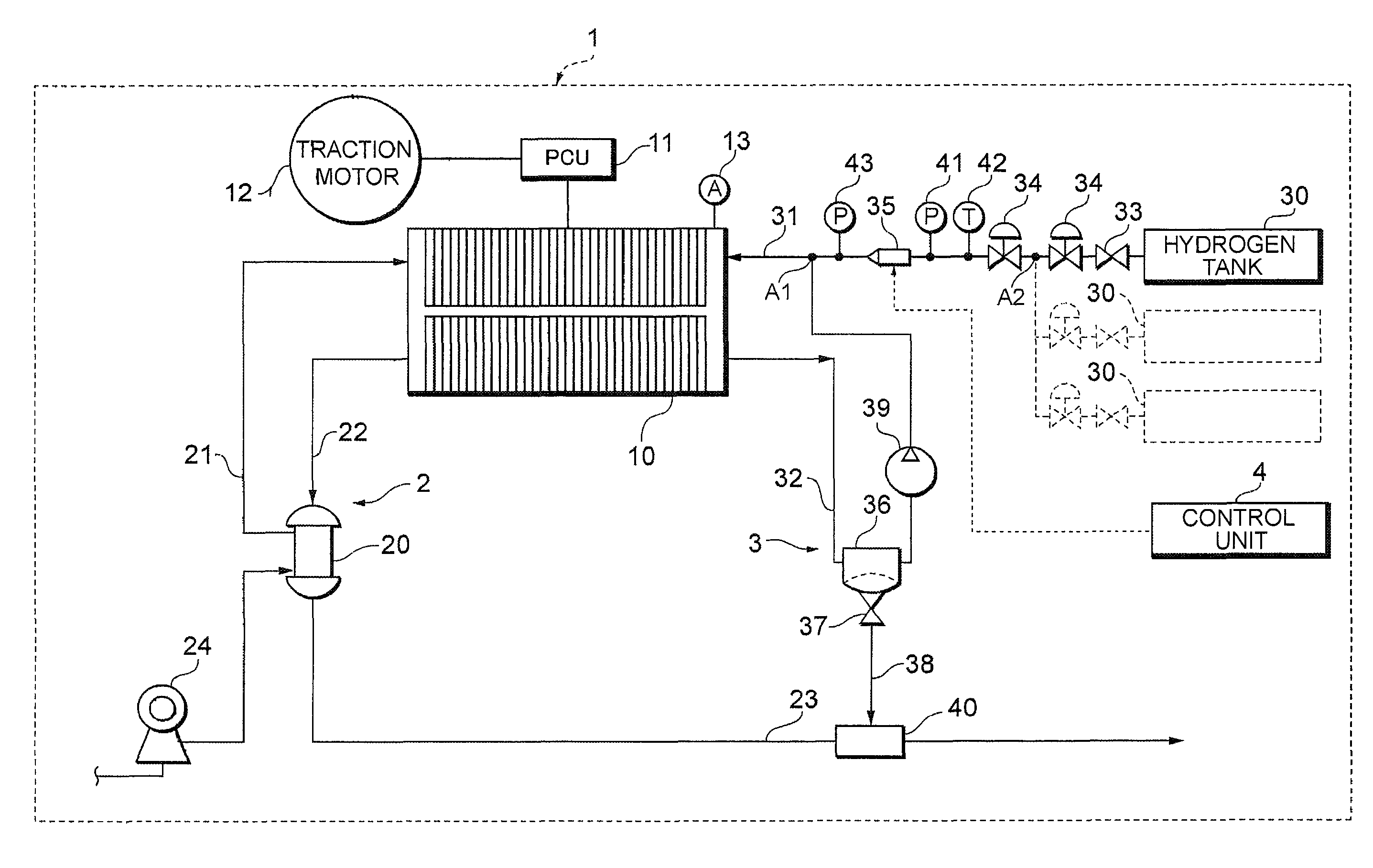
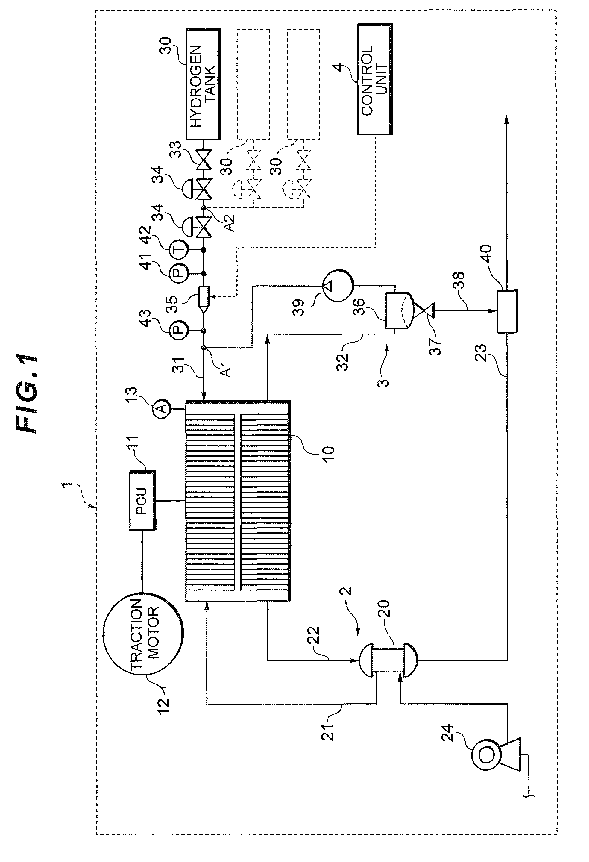
[0035]A fuel cell system 1 according to an embodiment of the present invention will hereinafter be described with reference to the drawings. In the present embodiment, an example in which the present invention is applied to a car-mounted power generation system of a fuel cell vehicle (a mobile body) will be described. First, a constitution of the fuel cell system 1 according to the embodiment of the present invention will be described with reference to FIG. 1.

[0036]As shown in FIG. 1, the fuel cell system 1 according to the present embodiment includes a fuel cell 10 which receives the supply of a reactant gas (an oxidizing gas and a fuel gas) to generate power, and further includes an oxidizing gas piping system (a fuel supply system) 2 which supplies air as an oxidizing gas to the fuel cell 10, a hydrogen gas piping system 3 which supplies a hydrogen gas as a fuel gas to the fuel cell 10, a control unit (control device, learning device) 4 which generally controls the whole system a...


PUM

PropertyMeasurementUnit
pressureaaaaaaaaaa
pressureaaaaaaaaaa
temperatureaaaaaaaaaa

Abstract

A basic injection time of an injector is obtained from an FC current detected in step S1. The basic injection time based on the FC current is multiplied by a predetermined correction coefficient for correction (learning), and the thus obtained value is re-defined as the basic injection time to obtain an injection time feedforward term (F / F term) to be obtained finally. The correction coefficient K is set by obtaining a flow rate characteristic per unit drive time of the injector in accordance with the relation between a total drive time and a total injection quantity of the injector until an FC inlet pressure on the anode side of a fuel cell reaches a predetermined target pressure by increasing the FC inlet pressure to the target pressure at a system start. The correction coefficient K is updated every system start.

Description

[0001]This is a 371 national phase application of PCT / JP2007 / 061395 filed 29 May 2007, which claims priority to Japanese Patent Application No. 2006-158644 filed 7 Jun. 2006, the contents of which are incorporated herein by reference.TECHNICAL FIELD[0002]The present invention relates to a fuel cell system including a fuel cell for receiving the supply of a reactant gas (a fuel gas and an oxidizing gas) to generate power.BACKGROUND ART[0003]At present, a fuel cell system including a fuel cell for receiving the supply of a reactant gas (a fuel gas and an oxidizing gas) to generate power has been suggested and put to practical use. Such a fuel cell system is provided with a fuel supply passage for feeding, to the fuel cell, the fuel gas supplied from a fuel supply source such as a hydrogen tank.[0004]Furthermore, a fuel cell system including a variable pressure adjustment valve as a pressure adjustment valve provided on the fuel supply passage so as to adjust the pressure of the fuel g...

Claims


Application Information

Patent Timeline
Patent Type & Authority Patents(United States)
IPC IPC(8): H01M8/04
CPCH01M8/04097H01M8/04223H01M8/04328H01M8/04388H01M8/04589H01M8/04753H01M8/04992H01M8/04231Y02E60/50H01M8/2457H01M8/04302H01M8/04225H01M8/04
Inventor UMAYAHARA, KENJI
Owner TOYOTA JIDOSHA KK
Why Eureka
Try Eureka