Evaporator for a refrigeration circuit

a refrigeration circuit and evaporator technology, applied in the direction of cooling fluid circulation, lighting and heating apparatus, domestic cooling apparatus, etc., can solve the problems of unfavorable evaporator design, unfavorable evaporator generalization, and uneven heat dissipation across the entire evaporator, and achieve the effect of simple design

Inactive Publication Date: 2013-12-31
BEHR GMBH & CO KG
View PDF11 Cites 38 Cited by
  • Summary
  • Abstract
  • Description
  • Claims
  • Application Information

AI Technical Summary

Benefits of technology

[0007]The heat-exchanger element enables the refrigerant which emerges from the evaporator region to overheat in that heat is transferred in a defined manner from the inlet-side refrigerant flow to the emerging refrigerant flow. This makes it possible in particular for the refrigerant to flow through the evaporator region without overheating, or with only minimal overheating. The refrigerant can therefore also be present in the entire evaporator region as wet steam phase. A refrigerant in the sense of the invention is understood to be any suitable means for operating a refrigeration circuit, in particular in addition to conventional refrigerants such as R134a and CO2. The first expansion device in the sense of the invention is understood to be any suitable expansion device, such as a fixed restriction, a thermostatic expansion valve (TXV), or even an electronically controlled expansion valve. Since the first expansion device is disposed upstream of the heat-exchanger element, the heat-exchanger element can also be considered to be an internal low-pressure heat exchanger of the refrigeration circuit. The evaporator according to the invention therefore comprises an evaporator region which exchanges heat mainly with the exterior region, and the heat-exchanger element which brings about mainly an internal heat exchange.
[0008]In an embodiment of the invention, a second expansion device is provided on the inlet side, between the heat-exchanger element and the evaporator region. As a result, the inlet-side portion of the heat-exchanger element disposed upstream of the evaporator region can transfer an amount of enthalpy to the outlet-side refrigerant flow in a particularly effective manner. To simplify the design, the second expansion element is preferably a fixed restriction, the size of which is selected accordingly. Depending on the requirements, the second expansion element can also be controllable, either alternatively or in addition to a controllable design of the first expansion element.
[0017]According to a preferred, low-cost, and simple design, the heat sink has a plate-sandwich design in the evaporator region at least. Such a design of a plate-type evaporator is described, for example, in document DE 195 28 116 B4, which corresponds to U.S. Pat. No. 5,836,383, which is incorporated herein by reference, and in which case a plurality of layers of interrupted—and solder-plated in particular—plates are stacked one above the other in the manner of a sandwich to form channels for the refrigerant. The heat-exchanger element also can have a plate-sandwich design, in particular as a structural unit with the evaporator region.

Problems solved by technology

As a result, the thermal capacity is not distributed homogeneously across the entire evaporator.
This is undesired in general for evaporators used for air conditioning, and to a particular extent for cooling heat sources, in which case it is particularly important to remain within a preferred temperature range.

Method used


Image

  • Evaporator for a refrigeration circuit
  • Evaporator for a refrigeration circuit
  • Evaporator for a refrigeration circuit

Examples


Embodiment Construction

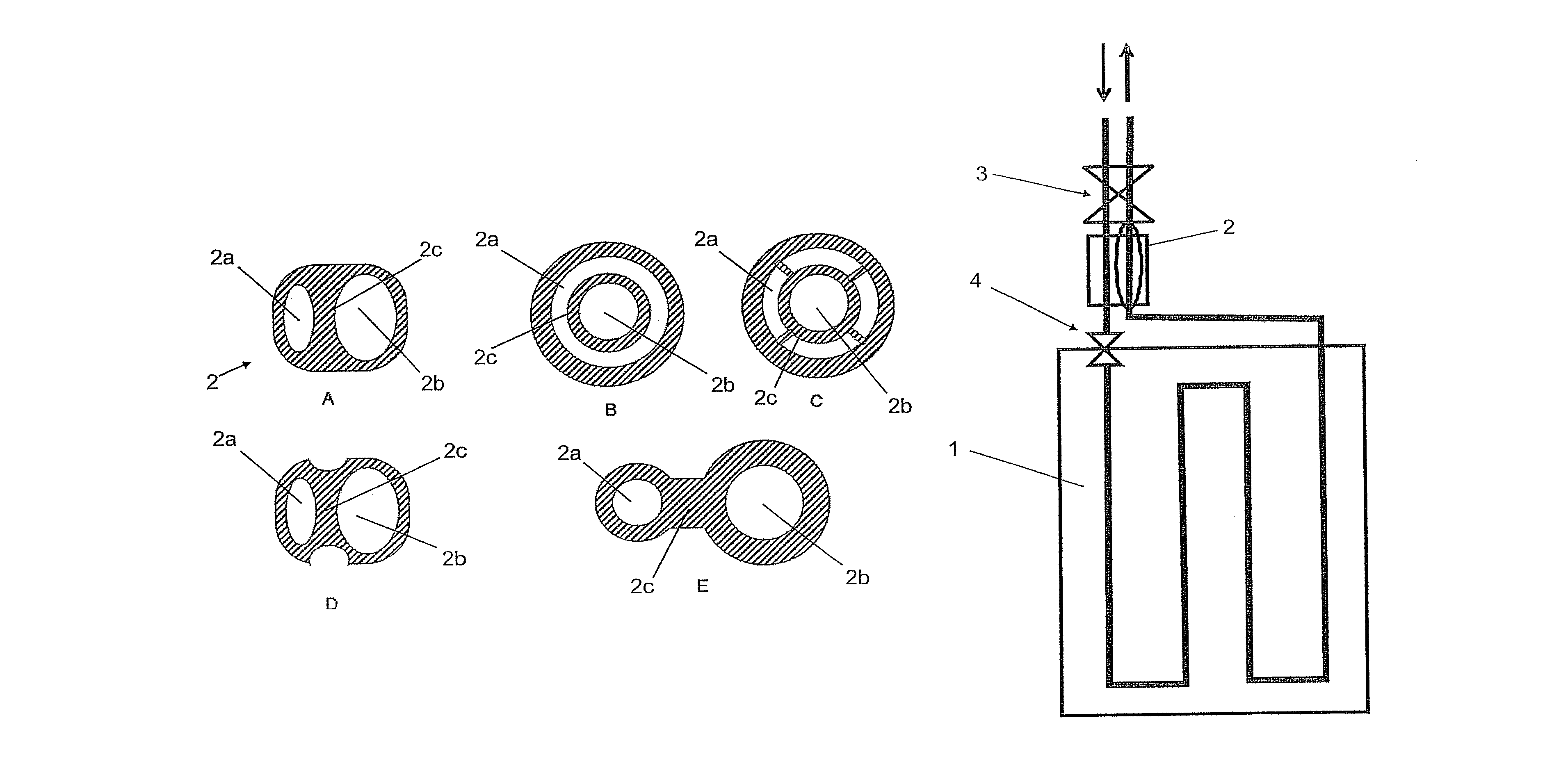
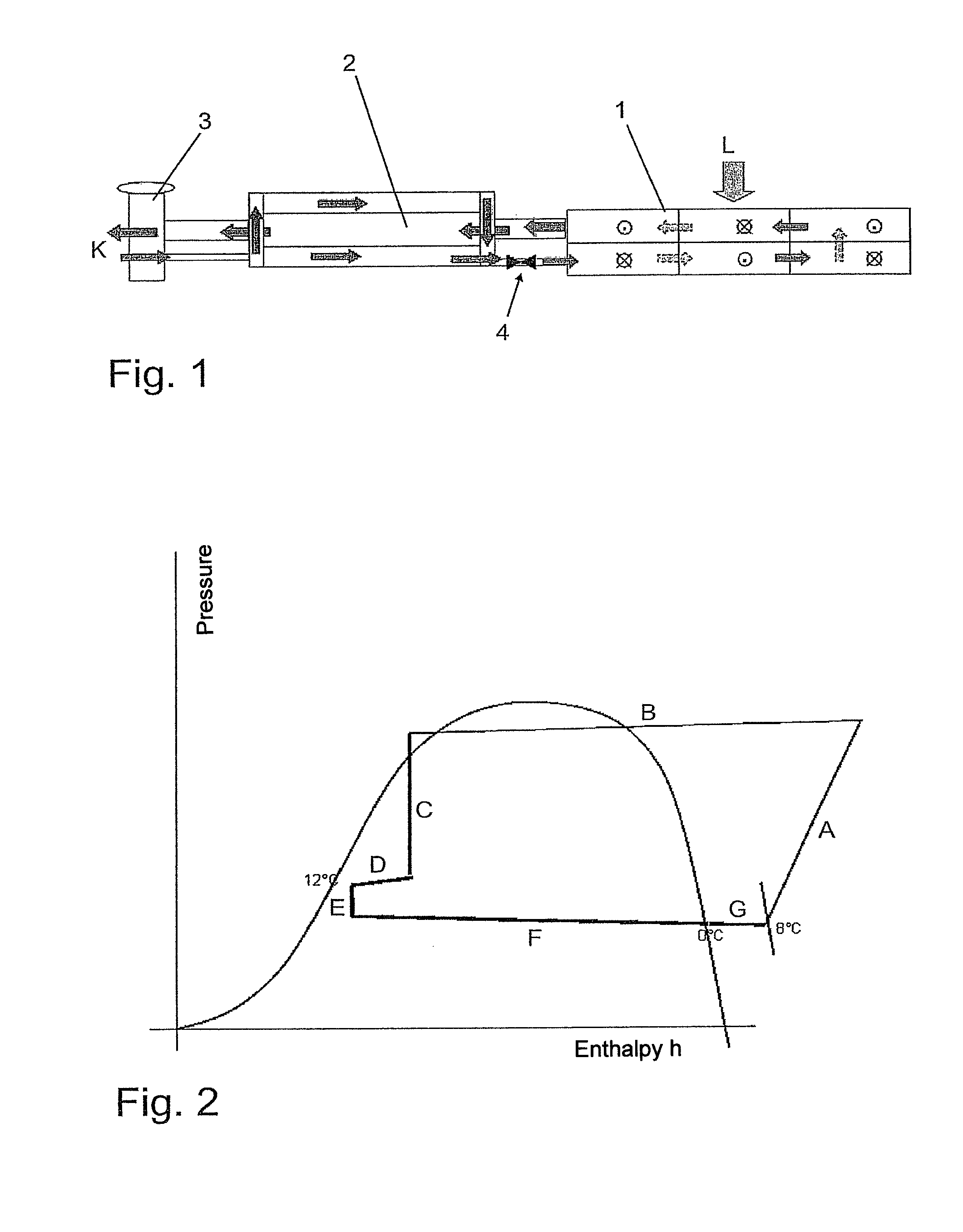
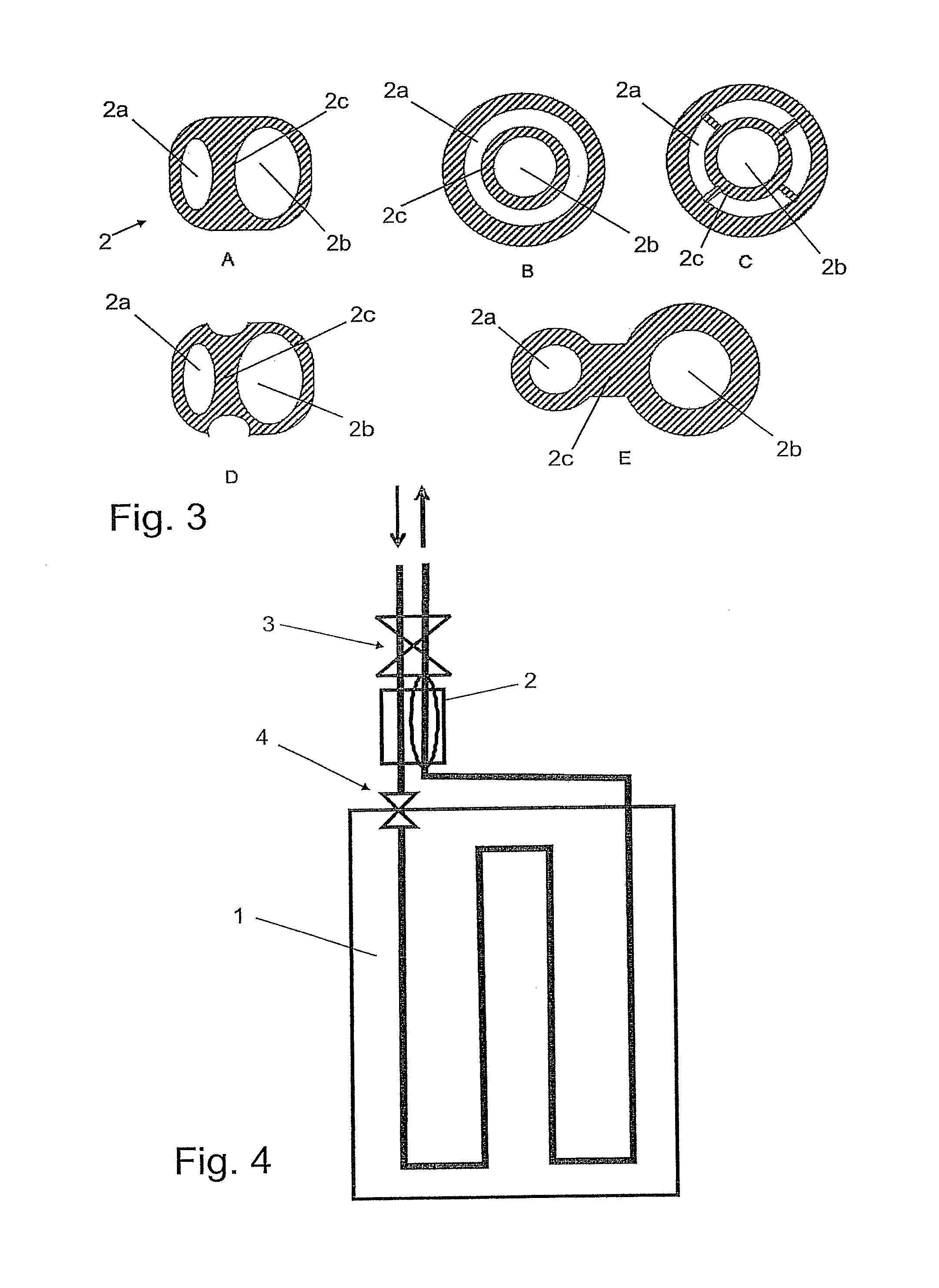
[0027]The evaporator shown in FIG. 1 comprises an evaporator region 1 and a heat-exchanger element 2 attached thereto. Evaporator 1 is designed as a flat-tube evaporator for conditioning air L for a passenger compartment. To optimize the capacity thereof and improve homogeneity, it is divided into six blocks in the present case, through each of which a refrigerant K flows in succession. The evaporator region is therefore in the form of a heat exchanger that is thermally connected to the exterior region, wherein the heat-exchanger element is substantially in the form of an internal heat exchanger.

[0028]A thermostatic expansion valve 3, as a first expansion device, is disposed upstream of heat-exchanger element 2, wherein an inflowing stream of refrigerant is regulated by expansion valve 3. The stream of refrigerant emerging from the evaporator likewise flows through the expansion valve, and is regulated depending on the pressure and temperature of the emerging stream. Overheating of ...


PUM


Abstract

A vaporizer for a cooling circuit, particularly for a motor vehicle, is provided that includes a vaporization region, wherein a coolant flowing through the vaporization region takes up heat from an outside region, wherein the vaporization region is downstream of a first expansion element on the inlet side in the direction of flow of the coolant, wherein an exchanger member is provided between the vaporization region and the first expansion element, and wherein heat can be transferred from the coolant upstream of the vaporization region to the coolant downstream of the vaporization region.

Description

[0001]This nonprovisional application is a continuation of International Application No. PCT / EP2009 / 065852, which was filed on Nov. 25, 2009, and which claims priority to German Patent Application No. DE 10 2008 060 699.5, which was filed in Germany on Dec. 8, 2008, and which are both herein incorporated by reference.BACKGROUND OF THE INVENTION[0002]1. Field of the Invention[0003]The present invention relates to an evaporator for a refrigeration circuit, in particular for a motor vehicle and to an operating method for such an evaporator.[0004]2. Description of the Background Art[0005]It is known to regulate the flow of refrigerant through the evaporator of a refrigeration circuit, e.g. using a thermostatic expansion valve, in order to ensure overheating of the refrigerant on the outlet side of the evaporator or on the intake side of a compressor of the refrigeration circuit. As a result, the thermal capacity is not distributed homogeneously across the entire evaporator. This is unde...

Claims


Application Information

Patent Timeline
Patent Type & Authority Patents(United States)
IPC IPC(8): F25D17/06
CPCF25B41/062F25B39/02F25B2341/0662F25B2341/064F25B2600/21F25B2400/054F25B40/00F25B2500/18F25B41/39
Inventor DUERR, GOTTFRIEDFEUERECKER, GUENTHERHIRSCH, STEFANISERMEYER, TOBIASSCHMID, CAROLINEWALTER, CHRISTOPHWIEBELT, ACHIM
Owner BEHR GMBH & CO KG
Why Eureka
Try Eureka