Asymmetrical brake torque plate back leg

a technology of asymmetrical brake torque and back leg, which is applied in the field of air brakes and asymmetrical brake torque plates, can solve the problems of undesirable vibration, as noted above, and achieve the effects of reducing vibration in the brake system, reducing the symmetry of the brake torque plate, and reducing the vibration of the braking system

Active Publication Date: 2013-12-31
THE BF GOODRICH CO
View PDF10 Cites 8 Cited by
  • Summary
  • Abstract
  • Description
  • Claims
  • Application Information

AI Technical Summary

Benefits of technology

[0007]An apparatus in accordance with the present invention reduces vibration in brakes, such as aircraft brakes, that utilize conical brake torque plates. As used herein, a brake torque plate refers to the combination of a torque tube and a back leg. A brake torque plate in accordance with the invention is formed so as to reduce symmetry of the brake torque plate (e.g., by including apertures placed asymmetrically around a circumference of the brake torque plate back leg). The brake torque plate with asymmetrically placed apertures significantly reduces vibration in the braking system.
[0008]Moreover, the reduced vibration can provide more consistent brake friction from cycle to cycle for each braking condition (e.g., landing, taxi stop). Brakes equipped with reduced symmetry brake torque plates in accordance with the invention also have been found to provide less variation between hot and cold taxi friction, which provides a more consistent pedal feel for the pilot and may promote improved wear rates.

Problems solved by technology

However, it has been discovered that conical shape brake torque plate back legs can contribute to or amplify vibration created by or introduced to the braking system.
These vibrations, as noted above, are undesirable.

Method used


Image

  • Asymmetrical brake torque plate back leg
  • Asymmetrical brake torque plate back leg
  • Asymmetrical brake torque plate back leg

Examples


Embodiment Construction

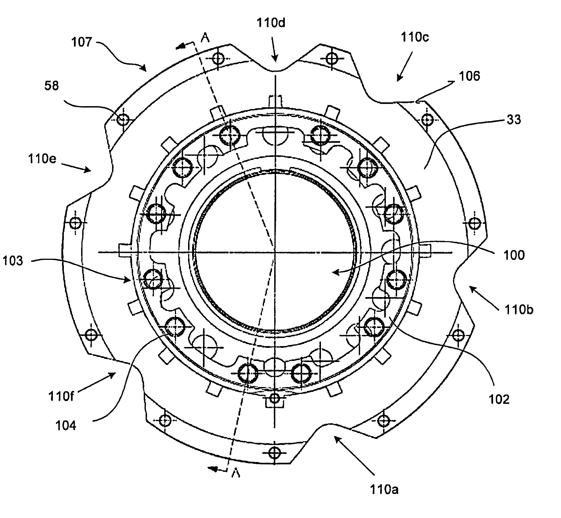
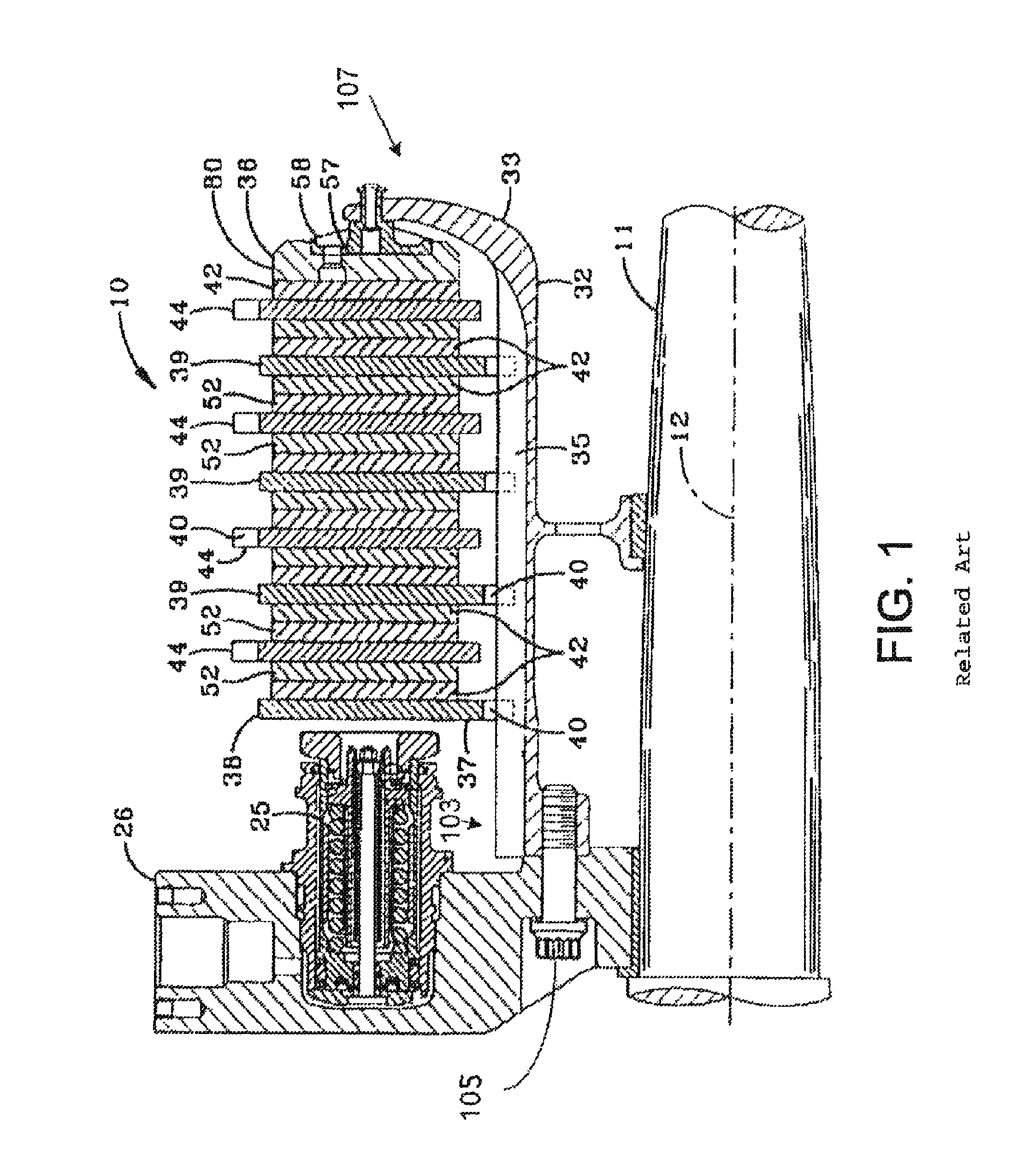
[0021]Referring to the drawings, wherein like reference numerals designate like or corresponding parts throughout the several views, there is schematically depicted in FIG. 1 a friction brake mechanism 10 mounted on axle 11 for use with a wheel (not illustrated) rotatable about axial centerline 12 in a manner fully described in U.S. Pat. No. 4,018,082 to Rastogi et al., U.S. Pat. No. 4,878,563 to Baden et al., and U.S. Pat. No. 5,248,013 to Hogue et al. The friction brake mechanism 10 includes a pressure plate 38 adjacent the hydraulic piston motor 25, an end plate 36 distal from the piston motor, and a plurality of interleaved rotor disks 44 and stator disks 39 which together form the brake heat sink or brake stack. The friction brake mechanism 10 also includes a torque plate 32, 33 on which the pressure plate 38, end plate 36 and stator disks 39 are slidably mounted against rotation relative to the wheel and rotor disks 44.

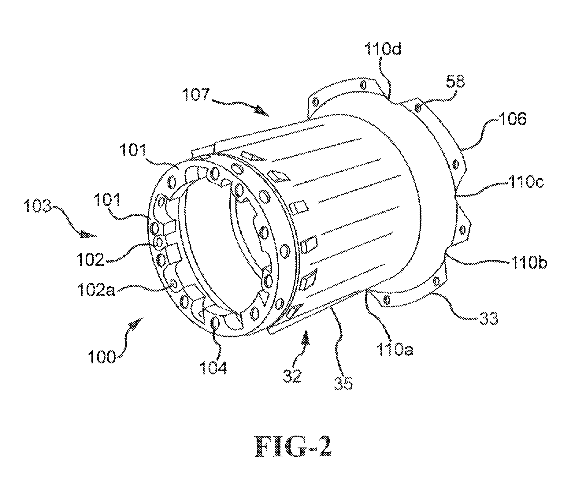
[0022]Torque plate 32, 33 includes an annular brake torque...


PUM


Abstract

A brake comprising a brake disk stack including stators alternating with rotors that are rotatable relative to the stators about an axis of the disk stack, an annular torque plate at one axial end of the brake disk stack, and a circumferential arrangement of actuators at the other axial end of the brake disk stack for urging the brake disk stack against the torque plate thereby to effect a braking force on the rotors. A back leg (33) of the annular torque plate includes a plurality of apertures (110a-110f) arranged asymmetrically around the axis of the brake disk stack.

Description

CROSS-REFERENCE TO RELATED APPLICATIONS[0001]This application is a U.S. National Phase filing under 35 U.S.C. 371 and claims priority to PCT Application No. PCT / US08 / 64313, filed on May 21, 2008, and entitled “ASYMMETRICAL BRAKE TORQUE PLATE BACK LEG,” which claims priority to U.S. Provisional Patent Application Ser. No. 60 / 939,192, filed May 21, 2007, both of which are incorporated herein by reference in their entirety.FIELD OF THE INVENTION[0002]The present invention relates generally to brakes and, more particularly, to an aircraft brake that includes an asymmetrical brake torque plate.BACKGROUND OF THE INVENTION[0003]Aircraft wheel and brakes heretofore have included a non-rotatable wheel support, a wheel rotatably mounted to the wheel support, and a brake disk stack having alternating rotor and stator disks mounted with respect to the wheel support and wheel for relative axial movement. Each rotor disk is coupled to the wheel for rotation therewith and each stator disk is coupl...

Claims


Application Information

Patent Timeline
Patent Type & Authority Patents(United States)
IPC IPC(8): F16D55/36
CPCF16D65/0006F16D55/40F16D55/36F16D2065/1364F16D2055/0058
Inventor BADEN, BRADLEY, J.
Owner THE BF GOODRICH CO
Why Eureka
Try Eureka