Rotation angle detection device, and rotation angle detection method

a detection device and detection method technology, applied in the direction of instruments, mechanical measuring arrangements, digital computer details, etc., can solve problems such as cost increase, and achieve the effect of sufficient cost reduction

Active Publication Date: 2013-12-31
TOYOTA JIDOSHA KK
View PDF25 Cites 2 Cited by
  • Summary
  • Abstract
  • Description
  • Claims
  • Application Information

AI Technical Summary

Benefits of technology

[0007]The invention provides a rotation angle detection device capable of univocally detecting detection angle that corresponds to the rotation angle while achieving sufficient cost reduction.

Problems solved by technology

However, the foregoing rotation angle detection device described in Japanese Patent Application Publication No. 2007-127609 (JP-A-2007-127609) has a problem as follows.
That is, in the case where the range of the rotation angle that is a detection object of the column main shaft deviates from the unit range of the rotation angle detection device, that is, in the case where a mounting error occurs, the detection angle that univocally corresponds to the rotation angle cannot be detected without going through the mounting operation again, and therefore a cost increase will result.

Method used


Image

  • Rotation angle detection device, and rotation angle detection method
  • Rotation angle detection device, and rotation angle detection method
  • Rotation angle detection device, and rotation angle detection method

Examples


Embodiment Construction

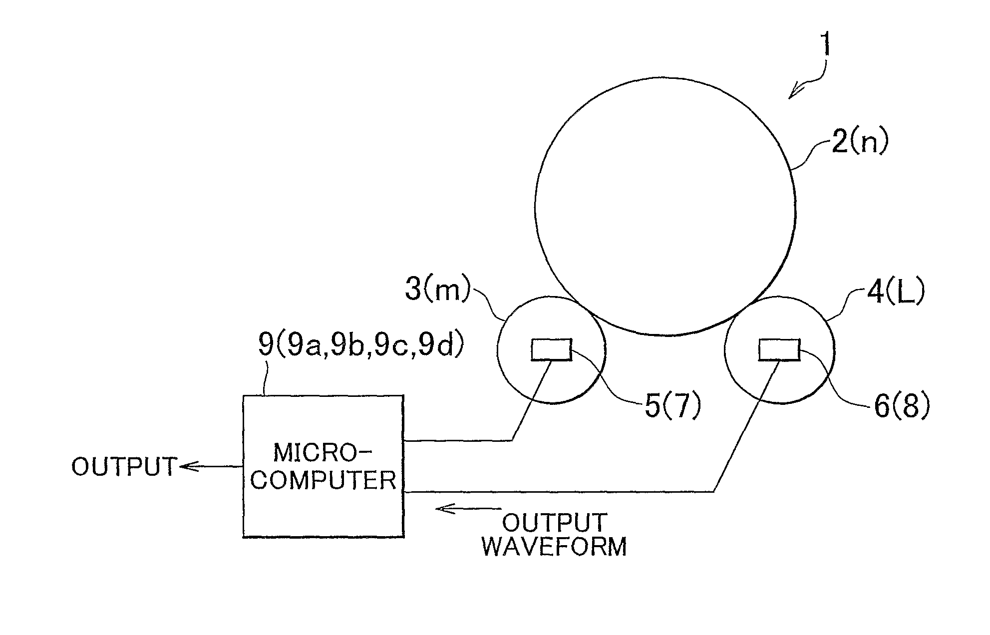
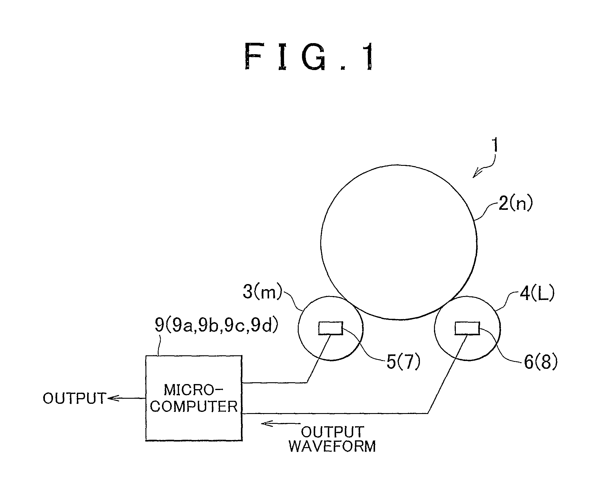
[0037]Embodiments for carrying out the invention will be described hereinafter with reference to the accompanying drawings. FIG. 1 is a schematic diagram showing a rotation angle detection device in accordance with an embodiment of the invention. Incidentally, the construction of this rotation angle detection device is well-known as described in Japanese Patent Application Publication No. 2007-127609 (JP-A-2007-127609). Therefore, in conjunction with this application, only component elements related to the invention are shown in the drawings, and other component elements are omitted from the drawings, and the descriptions of computations and detection principles is also omitted.

[0038]A rotation angle detection device 1 of this embodiment includes a main gear 2, a detecting gear 3, a detecting gear 4, a magnet 5, a magnet 6, a magnetic resistance element 7, a magnetic resistance element 8, and a microcomputer 9 as shown in FIG. 1.

[0039]The main gear 2 is drivingly coupled to a column...


PUM


Abstract

A rotation angle detection device includes: a detection portion that detects detection angle that univocally corresponds to rotation angle of a rotating body which is within a predetermined range, wherein the detection angle linearly increases from a minimum value to a maximum value as the rotation angle increases within a unit range, and the detection angle changes from the maximum value to the minimum value or from the minimum value to the maximum value at a boundary between unit ranges that are adjacent to each other; and a correction portion that corrects the detection angle so that the detection angle detected in the predetermined range has linear characteristics, if the boundary between the unit ranges is contained in the predetermined range.

Description

BACKGROUND OF THE INVENTION[0001]1. Field of the Invention[0002]The invention relates to a rotation angle detection device and a rotation angle detection method that are applied to vehicles such as passenger automobiles, trucks, buses, etc.[0003]2. Description of the Related Art[0004]As a rotation angle detection device that detects the rotation angle of a steering wheel of a motor vehicle, that is, the steering angle, an absolute angle sensor type device as described in Japanese Patent Application Publication No. 2007-127609 (JP-A-2007-127609) has been disclosed. This type of rotation angle detection device includes a main gear that is pivoted integrally with a column main shaft coupled to a steering wheel, two detection gears that are meshed with the main gear, and that each have a built-in magnet and that have different numbers of teeth, two magnetic resistance elements that face the magnets and that each magnetically detect the rotation angle of a corresponding one of the two de...

Claims


Application Information

Patent Timeline
Patent Type & Authority Patents(United States)
IPC IPC(8): G01B7/30
CPCG01D5/244G01D2205/26
Inventor KOJIMA, HIROYOSHIMURE, MASASHINISHIKAWA, HISASHI
Owner TOYOTA JIDOSHA KK
Why Eureka
Try Eureka