A drive supporting structure and a drive support element

a technology of supporting structure and supporting element, which is applied in the direction of mixers, special foundation layouts, domestic objects, etc., can solve the problems of raising the price of the supporting structure, problems such as straightness and right height, and achieve the effect of reducing a lot of costs

Inactive Publication Date: 2016-05-05
OUTOTEC FINDLAND OY
View PDF0 Cites 3 Cited by
  • Summary
  • Abstract
  • Description
  • Claims
  • Application Information

AI Technical Summary

Benefits of technology

[0010]An advantage of the drive supporting structure and the drive support element of the invention is that quality of the housing of the drive support element which is fabricated by casting is higher than in the case in which the drive support element is a welded structure. The price is lower for the casting element and the drive supporting structure may be packed and transferred as a split shipment to workshops and then assembled there which reduces a lot of costs. The drive supporting structure according to the invention enables modular product with just one cast element such that other steel parts are connected to the cast element for example with a bolt connection. If a bigger size gear is needed the drive support element can be further machined or replaced with a new one and the same support beam structure can still be used or as alternative the housing of the drive support element can be used and just change the upper part of the housing, i.e. a steel plate or similar. Another advantage with the drive support element comprising a housing fabricated by casting is that the same cast model can be used for the whole gear series.

Problems solved by technology

Problems with straightness and right height may arise after machining the parts which has to be taken into account to ensure that drive gear fits to the drive support.
The welded supporting framework and the welded drive support raise the price of the drive supporting structure because machining is also needed.

Method used


Image

  • A drive supporting structure and a drive support element
  • A drive supporting structure and a drive support element

Examples


Embodiment Construction

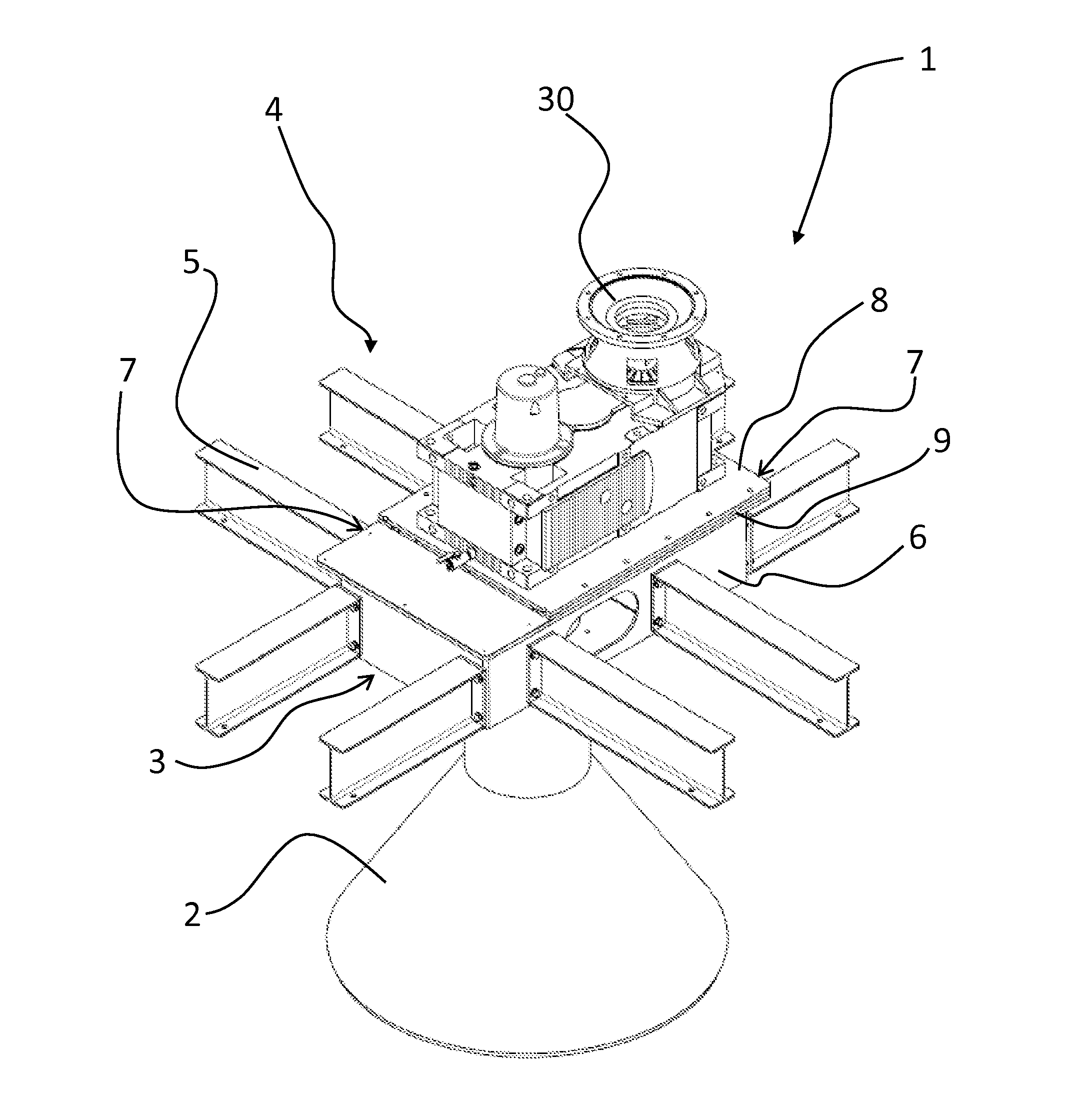
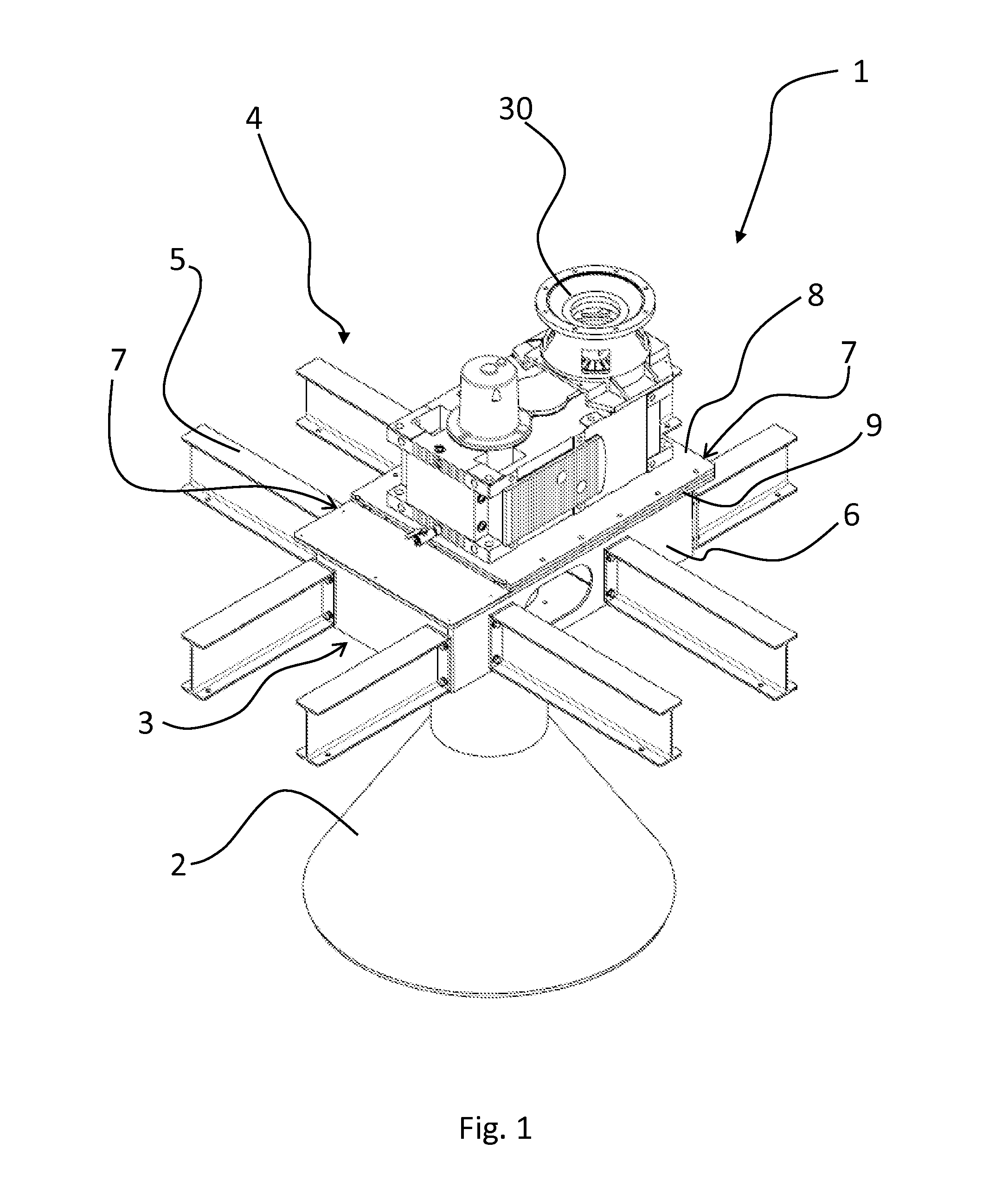
[0013]FIG. 1 is shows a drive supporting structure 1 for a tank 2. The drive supporting structure 1 comprises a drive support element 3 for supporting a drive 30 and a support beam structure 4 for supporting the drive support element 3. The support beam structure 4 is arranged on top side of the tank 2 and it comprises multiple support beams 5. The support beams 5 are preferably steel profiles, such as I-beams which are attachable to each other by bolt connections. The bolt connection enables the support beam structure 4 to be disassembled and packed in a package if it needs to be transferred to another place or the support beam structure 4 can be transferred to the working site in a compact package. The bolt connection enables an easy and fast support beam structure 4 assembly in the working site such that no extra time is spent on putting the support beam structure 4 together. The drive support element 3 for supporting a drive 30 in a tank 2 comprises a housing 6, which said housi...


PUM


Abstract

The invention relates to a drive supporting structure (1) for a tank (2). The drive supporting structure (1) comprises a drive support element (3) for supporting a drive (30) and a support beam structure (4) for supporting the drive support element (3). The support beam structure (4) is arranged on top side of the tank (2) and comprises multiple support beams (5). The drive support element (3) comprises housing (6), which said housing (6) is fabricated by casting. The support beam structure (4) is detachably connected to the drive support element (3) for forming a connection between the drive support element (3) and the support beam structure (4). The invention further relates to a drive support element (3) for supporting a drive in a tank (2). The drive support element (3) comprises housing (6), which is fabricated by casting.

Description

FIELD OF THE INVENTION[0001]The present invention relates to a drive supporting structure, and more particularly to a drive supporting structure as defined in the preamble of claim 1.[0002]The present invention also relates to a drive support element, and more particularly to a drive support element as defined in the preamble of claim 11.BACKGROUND OF THE INVENTION[0003]The present invention relates especially to solvent extraction technology in which solvent extraction tanks are used in a solvent extraction phase of the process. The present invention can also be used in tanks treating solid-liquid, gas-liquid, gas-solid-liquid and liquid-liquid systems for leaching, precipitation, crystallization, oxidation and reduction as well as in solvent extraction. A tank used in above mentioned processes typically comprises a cylindrical side wall, a bottom part and usually but not always a cover part. The tank comprises an agitator arranged inside the tank in the middle part of it. The agit...

Claims


Application Information

Patent Timeline
Patent Type & Authority Applications(United States)
IPC IPC(8): F16M13/02B01J19/00
CPCB01J19/0066F16M13/02B01F27/09B01F27/80B01F35/323B01F35/3214F04D7/00F04D13/00F04D29/00
Inventor HAUTANIEMI, TIMOSAARIO, RAMIFREDRIKSSON, HENRIPAJALA, JUSSI
Owner OUTOTEC FINDLAND OY
Why Eureka
Try Eureka