Face driver

a driver and face technology, applied in the field of face drivers, to achieve the effect of facilitating play-free cooperation and facilitating cooperation of support pins

Inactive Publication Date: 2014-01-07
ROHM GMBH
View PDF25 Cites 2 Cited by
  • Summary
  • Abstract
  • Description
  • Claims
  • Application Information

AI Technical Summary

Benefits of technology

[0005]It is therefore an object of the present invention to provide an improved face driver.
[0007]A further object is to provide a face driver that may be integrated into the existing design of conventional face drivers, while at the same time reducing the difficulty of operation and maintenance.SUMMARY OF THE INVENTION
[0009]The face driver according to the invention is characterized by a very simple design in which the torque may be transmitted from the body coupled to the work spindle of the lathe, to the driver disk by the support pins that engage in the grooves of the driver disk, and as a result of the axial displaceability of the support pins the driver disk may be carried along in an oscillating manner; i.e., the driver disk may be adapted to inclined workpiece surfaces without impairing the holding or transmission of torque to the workpiece at its end face. The driver disk may have teeth on its front side facing the workpiece, although the invention may also be implemented using any other known variant for the contact between the end face of the workpiece and the driver disk.
[0011]It is also advantageous when at least three support pins are provided, and the compensating disk is spherically swivelable on the body on a bearing. This design provides a three-point bearing in which the ends of the support pin facing the driver disk are appropriately aligned via the spherical swiveling of the compensating disk on the body. Alternatively, inclined surfaces that are associated with the support pins may be provided on the compensating disk, by means of which the a planar face of the compensating disk is radially displaced on the body in a compensating manner.
[0012]According to the invention, the grooves have V-forming bevels for cooperating with the associated centering heads, thus in particular facilitating play-free cooperation of the support pins with the driver disk, and especially changing between right and left rotational directions without interfering with the oscillating drive. The cooperation of the three-point bearing and the guiding of the support pins in the V-forming bevels of the grooves prevents the driver disk from twisting, regardless of the direction of torque and the oscillating function.
[0013]To further facilitate cooperation of the support pins with the grooves in the driver disk, the centering heads have part-spherical front ends, so that the support pins are able to align in the V-forming bevels in the grooves via the spherical front ends, and to maintain this alignment regardless of the rotational direction of the work spindle. Within the scope of the invention, it is further provided that the centering rod extends through a central passage in the compensating disk; i.e. the compensating disk is on the centering rod and in this respect can swivel without slipping radially.

Problems solved by technology

As a result of the holding at the end faces, torque must be transmitted via the end faces of the workpiece, and in addition forces that act during axial and radial machining must not be allowed to interfere with the holding and the position of the workpiece.

Method used


Image

  • Face driver
  • Face driver
  • Face driver

Examples


Embodiment Construction

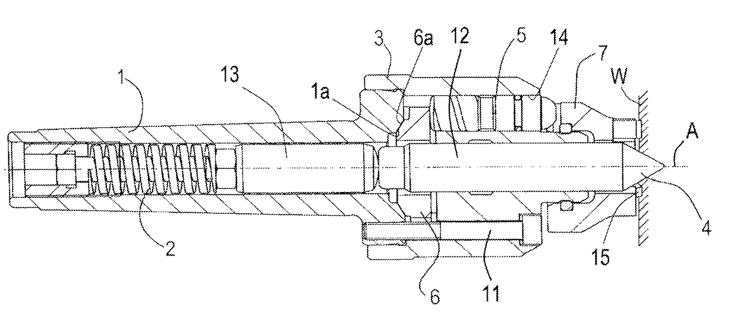
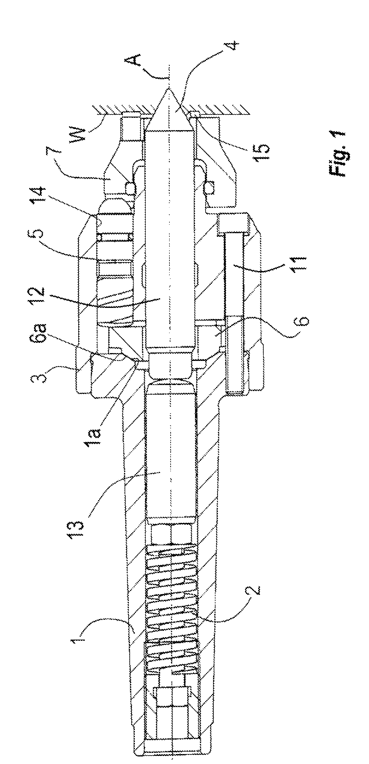
[0018]As seen in FIG. a face driver has a metallic body 1 centered on an axis and formed at its rear region with an external Morse taper for coupling to the work spindle of a lathe or the like. A compression spring 2 bears indirectly via a pusher rod 13 on a centering rod 12 having a point 4 fitted in an axially centered passage of the body 1 and the pressure it exerts is applied as a variable centering force to the point 4 that can dig into a workpiece shown schematically at W. The face driver also has an annular driver disk 7 that coaxially surrounds the centering rod 12 and can contact the workpiece W, as well as a driver head 3 in which a plurality of support pins 5 are axially slidable in respective guides 14 extending parallel to but offset radially from the center axis A. The driver head 3 is rotationally and axially fixed to the body 1 by angularly equispaced screws 11 that pass through the driver head 3 and engage in respective threaded holes in the body 1. Each support pin...


PUM


Abstract

A face driver has a body rotatable about an axis and a head rotationally fixed on the body and formed with a plurality of guides open axially forwardly toward a workpiece and radially offset from the axis. A centering rod axially shiftable in the body on the axis has a front-end point engageable with the face of the workpiece. A compression spring in the body urging the rod axially forward toward the workpiece, a driver disk has a front face engageable with the workpiece and a back face formed with a plurality of rearwardly open and radially extending grooves aligned with the guides. Respective support pins axially shiftable in the guides have heads engaged in the respective grooves so as to rotationally couple the driver disk rotationally to the body while permitting the driverd disk to tip with axial displacement of the pins.

Description

FIELD OF THE INVENTION[0001]The present invention relates to a face driver. More particularly this invention concerns such driver used in a lathe or the like for transmitting torque to an end face of a workpiece.BACKGROUND OF THE INVENTION[0002]A standard face driver has a body in which a compression spring is directly or indirectly braced against a centering rod having a centering point, and having a driver disk that surrounds the centering rod and serves for contacting the workpiece. Such a face drivers is used in cooperation with a tailstock to hold workpieces at their end faces when it is not possible to hold them on their side or peripheral surfaces, for example because that is where machining is to be done. As a result of the holding at the end faces, torque must be transmitted via the end faces of the workpiece, and in addition forces that act during axial and radial machining must not be allowed to interfere with the holding and the position of the workpiece.[0003]A face dri...

Claims


Application Information

Patent Timeline
Patent Type & Authority Patents(United States)
IPC IPC(8): B23B23/00
CPCB23B33/005Y10T82/26
Inventor SCHEU, RUDOLF
Owner ROHM GMBH
Why Eureka
Try Eureka