Detection method and device for array antenna calibration

An array antenna and detection method technology, applied in the field of communication, can solve the problems of increasing the difficulty of operation and maintenance, increasing the cost of hardware, etc.

Active Publication Date: 2019-12-27
DATANG MOBILE COMM EQUIP CO LTD
View PDF6 Cites 5 Cited by
  • Summary
  • Abstract
  • Description
  • Claims
  • Application Information

AI Technical Summary

Problems solved by technology

[0006] Obviously, this will increase additional hardware costs and increase the difficulty of later operation and maintenance

Method used


Image

  • Detection method and device for array antenna calibration
  • Detection method and device for array antenna calibration
  • Detection method and device for array antenna calibration

Examples


Embodiment Construction

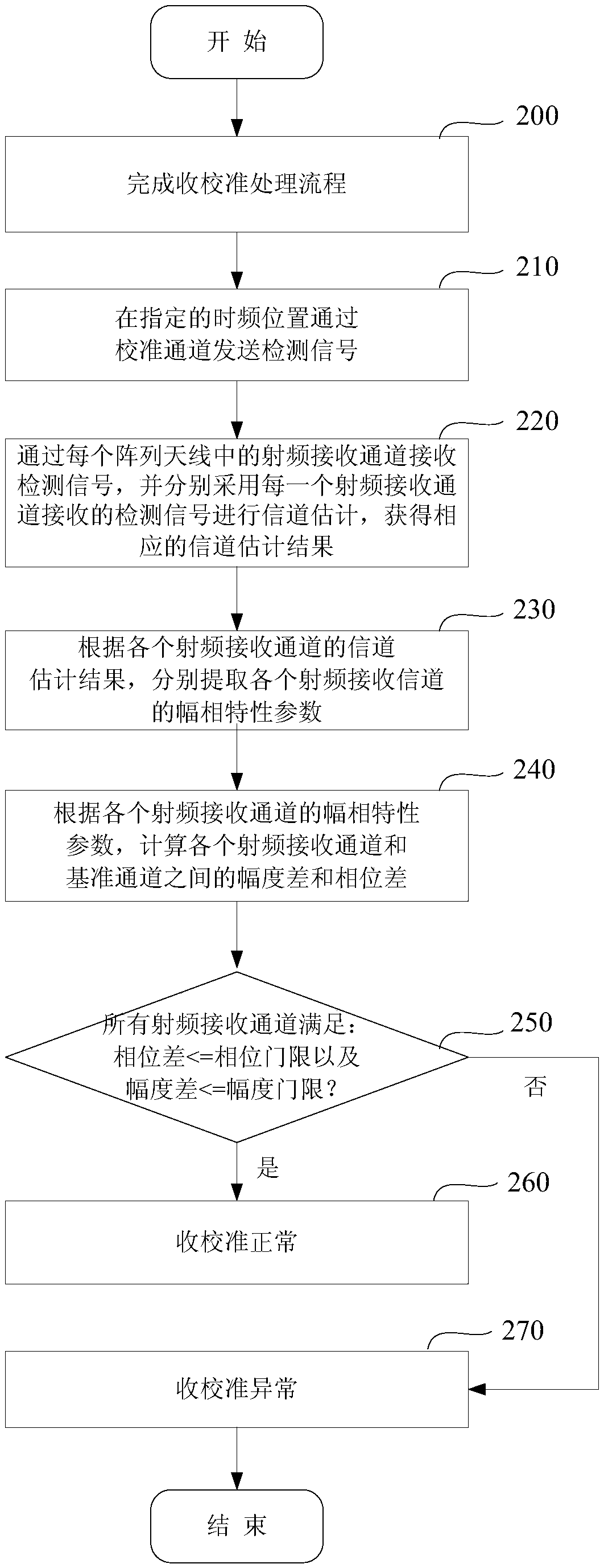
[0052] In order to avoid adding additional hardware costs during the detection process and reduce the difficulty of operation and maintenance in the later stage, in the embodiment of the present invention, instead of relying on a dedicated external terminal, the base station itself sends a detection signal and uses the radio frequency loopback method Receive the detection signal and process it, so as to achieve the purpose of self-detection and calibration effect.

[0053] Preferred embodiments of the present invention will be described in detail below in conjunction with the accompanying drawings.

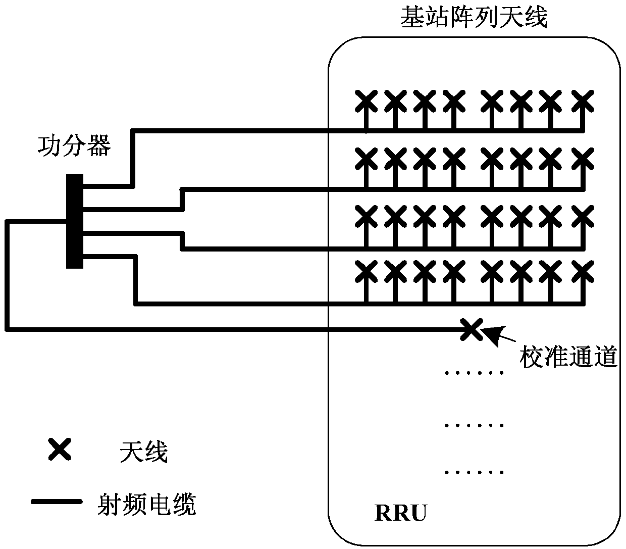
[0054] refer to figure 1 As shown, in the embodiment of the present invention, the internal structure of the base station (i.e. RRU) is as follows: each port of the array antenna (i.e. each port of the radio frequency channel) is connected to the branching end of the power splitter, and the combining end of the power splitter is connected to the The calibration channel in the bas...


PUM


Abstract

The invention relates to the field of communication, and discloses a detection method and device for receiving calibration of an array antenna, which are used for avoiding the increase of extra hardware cost in the detection process and reducing the later operation and maintenance difficulty. The method comprises the following steps of: ; after finishing receiving calibration, the base station performs receiving calibration; transmitting a detection signal from the calibration channel at a specified time domain position; the method comprises the following steps: acquiring a detection signal ofeach radio frequency receiving channel, looping the detection signal back to each radio frequency receiving channel through radio frequency so as to calculate amplitude-phase characteristic parameters of each radio frequency receiving channel, and finally determining that the receiving calibration is normal when determining that each radio frequency receiving channel meets the amplitude-phase consistency requirement based on the acquired amplitude-phase characteristic parameters. Thus, equipment hardware structures of existing base stations do not need to be changed, other external auxiliaryinstruments and meters do not need to be adopted, detection for the calibration effect can be smoothly completed only through hardware conditions of the base stations, accordingly, extra hardware costadded in the detection process is effectively reduced, and meanwhile the later operation and maintenance difficulty is reduced.

Description

technical field [0001] The invention relates to the communication field, in particular to a detection method and device for array antenna calibration. Background technique [0002] In the next-generation mobile communication technology, due to the emergence of multiple-input multiple-output (Multiple-Input Multiple-Output, MIMO) technology, array antennas will be widely used. However, in terms of physical implementation, the characteristic response of the radio frequency circuit of each antenna is difficult to achieve consistency in amplitude and phase due to differences in hardware technology, working environment and other conditions. [0003] Antenna radio frequency channel calibration technology is born with the emergence and application of array antennas. Its main function is to perform pre-compensation processing (including amplitude and phase) on each radio frequency channel, so that it can eliminate the radio frequency reception on each antenna in the array antenna. ...

Claims


Application Information

Patent Timeline
Patent Type & Authority Applications(China)
IPC IPC(8): H04B7/0413H04B17/21H04L25/02
CPCH04B7/0413H04L25/0202H04B17/21
Inventor 韩乾郭晴王希王国栋宗耀宗
Owner DATANG MOBILE COMM EQUIP CO LTD
Why Eureka
Try Eureka