
System for determining the flow rate in a fluid with liquid additives using reciprocating positive-displacement flow meter

a flow meter and positive displacement technology, applied in liquid transfer devices, process and machine control, instruments, etc., can solve the problems of increasing and affecting the accuracy of metering over time. , to achieve the effect of reducing or eliminating leakage and maintenance, accurate metering, and reducing the risk of additive introduction

Active Publication Date: 2014-01-14
HAMMONDS TECHN SERVICES
View PDF56 Cites 1 Cited by
  • Summary
  • Abstract
  • Description
  • Claims
  • Application Information

AI Technical Summary

Benefits of technology

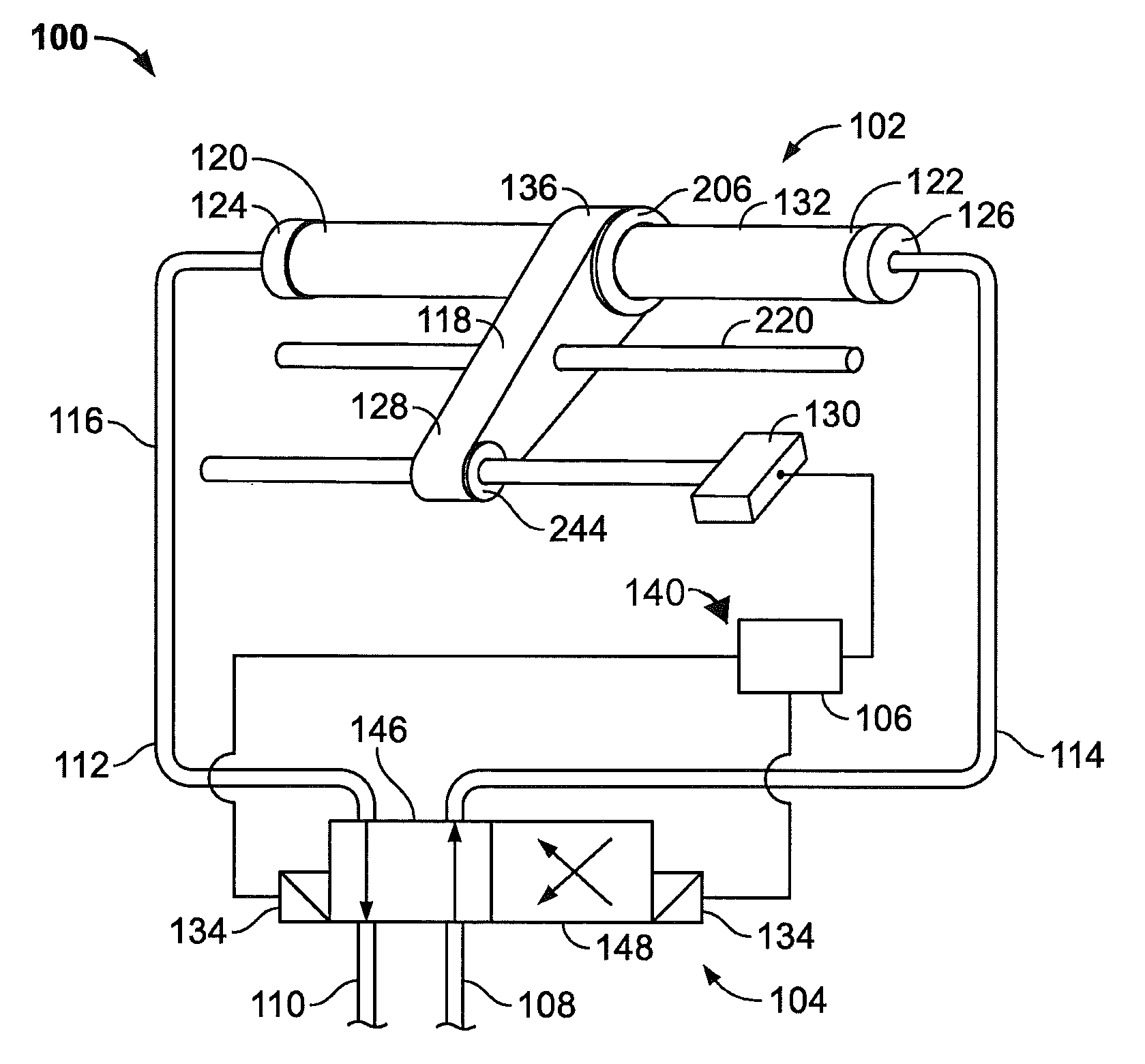
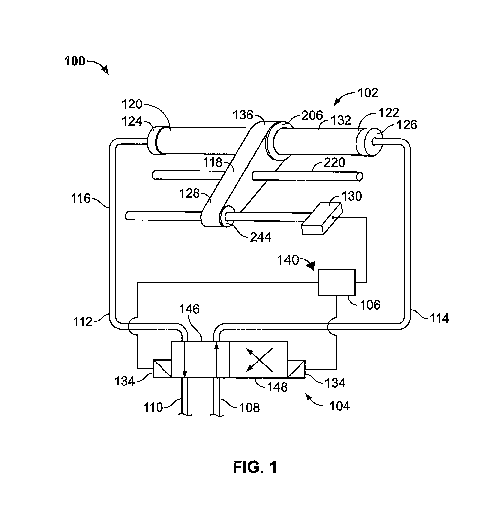
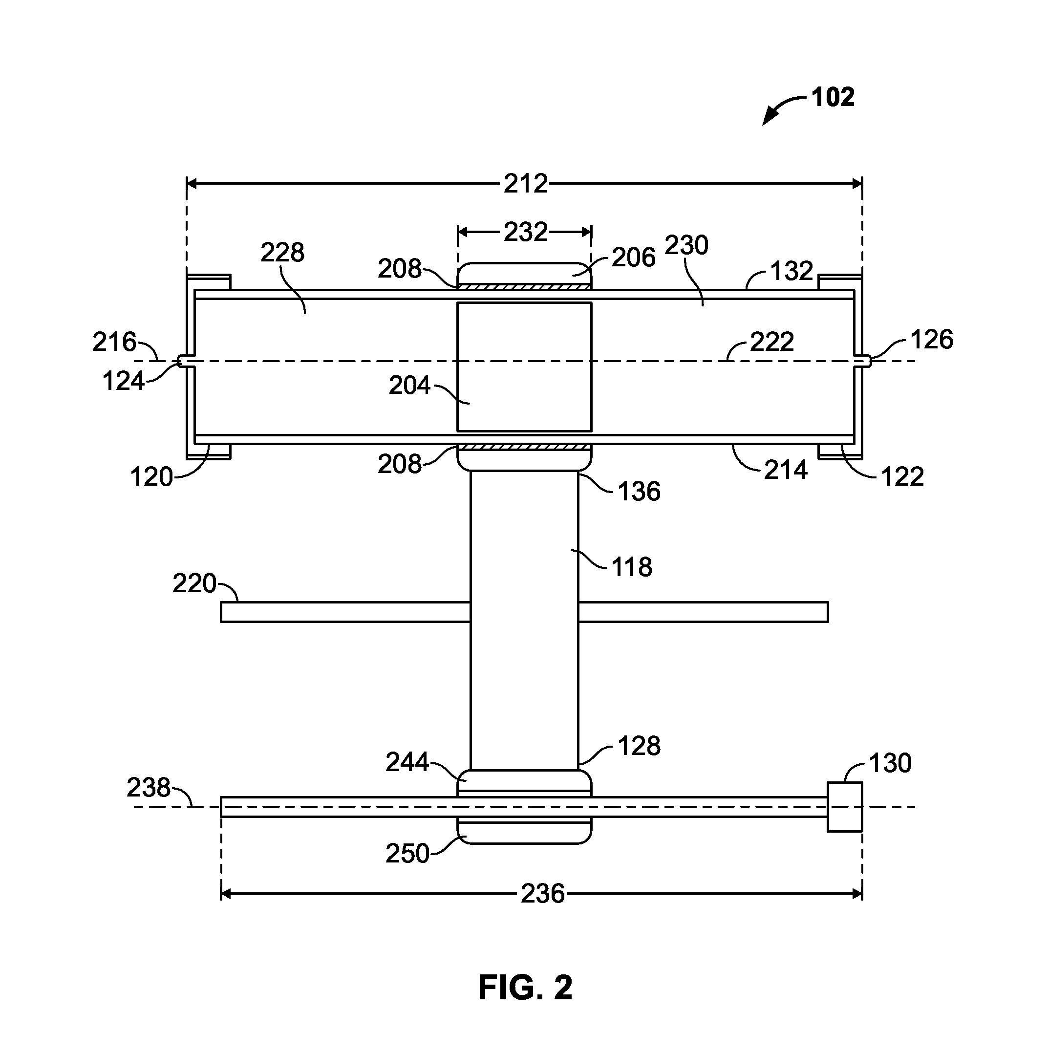
[0016]It is therefore, a principle object of the present invention to provide a flow meter, particularly a positive displacement reciprocating flow meter, which produces accurate metering with minimal moving parts and which is accurate over time, regardless of pump efficiency or system leakage. This achieved by providing a cylindrical body with fluid connectors at its sealed ends, a ferrous floating internal piston, a cylindrical ring freely encircling the cylindrical body and magnetically coupled to the ferrous floating internal piston, a high resolution linear digital encoding transducer (preferably cylindrical and absolute) preferably parallel to and equivalent in length to the cylindrical body, a coupling arm integrally affixed to the magnetic ring so as to function as a single unit therewith and having a magnetic section contacting the linear digital encoding transducer, with a valve system providing additive to reciprocate the ferrous floating internal piston and to dispense additive to the untreated fluid, and a computer adapted to determine the position of the coupling arm relative to said linear digital encoding transducer to determine position, and, by measurement of time and determination of change in direction, velocity and a valve controller to control the valve system to reciprocate the ferrous floating internal piston. The sealed ends of the cylindrical body and the magnetic coupling between the ferrous floating internal piston and the linear digital encoding transducer provide reduce or eliminate leakage and maintenance associated with meters since there are no dynamic seals involved.
[0022]Unlike the prior art, the present flow meter invention provides a high degree of accuracy by providing identification of the position of the piston in the reciprocating flow meter at all points between the ends of the flow meter. This particularly important as it provides an instantaneous, or real time, rate of flow. Thus, the lag time associated with the imprecision of measurements based on the total stroke of the piston through the flow meter is avoided. Delays in time of position data create a corresponding delay in the adjustments necessary to maintain the pre-set ratio. This lag time had historically been a problem in fuel additive delivery systems when the ratio of additive to untreated fluid was less than 1%. In operation, this results in an additive concentration of about 2500 PPM. In the fuel additive industry, anything over 2500 PPM or ¼% is considered blending and may be accomplished with the lower resolution flow meters or a rotary positive displacement device.

Problems solved by technology

Moreover, it is desirable to have a high turndown in these systems, although typically one of the most substantial problems with existing meters.
Existing meters thus have a narrow (often very narrow) range of operations, problematic in cases of fuel injection where flow may operate between zero flow and high flow rates.
Additionally, the cost of the additive to be introduced may be quite high, so cost-effectiveness requires the flow rate, as measured by a flow meter and potentially communicated to an associated logic controller which may in turn control the pump supplying the additive.
Introduction of additive at actual flow rates which are above or below the desired flow rate is undesirable, such as in cases where the additive is introduced to an untreated flow of a petroleum-based fluid where combustion may be over- or under-pressurized in the engine, potentially posing a danger to operators and others.
Such meters are prone to clogging and locking up as a result of various foreign material found in fluids such as additives or treating agents.
In addition, many fluids, additives or treating agents have solids that are a part of the fluid, additive or treating agent itself which tend to be highly abrasive.
This abrasiveness quickly wears the meter and causes it to quickly lose efficiency and its ability to accurately reflect the volume passing through the meter.
Additives such as dyes are very abrasive with a high solids content making them inappropriate for use with oval gear meters.
Oval gear meters require minimum flow rates that far exceed those rates found in additive injection, making them inoperable in these applications.
Such metering systems are of limited utility in measuring flow rates.
Float systems similarly are of limited benefit where the system is susceptible to being out of vertical alignment.
Where used for additive delivery in fuels, such metering systems are of limited utility, specifically where the volume of additive introduced is particularly small relative of the untreated fluid (such as less (preferably substantially less) than 0.25% or, non-equivalently less than 2500 parts per million (PPM) (additive to fuel)).
In addition to the foregoing, due to the minute amount of additive dispensed, and the long time needed for the typical reciprocating metering system to complete one cycle (and hence provide a flow rate) that real time flow rates cannot be obtained the resulting flow rate has not assurance that the resulting average is consistent with the dispensing rate throughout the cycle.

Method used


Image

  • System for determining the flow rate in a fluid with liquid additives using reciprocating positive-displacement flow meter
  • System for determining the flow rate in a fluid with liquid additives using reciprocating positive-displacement flow meter
  • System for determining the flow rate in a fluid with liquid additives using reciprocating positive-displacement flow meter

Examples


Embodiment Construction

[0032]The present flow meter invention involves the use of magnetically-coupled and sensitive devices to provide precise data to provide an instantaneous high resolution flow meter for monitoring the flow rate of a fluid in real time, even when measured in relatively small units and / or to precisely dispense relatively small volumes of liquid. The flow rate determination provided by the flow meter may be used to control the flow rate of fluid into the flow meter prior to disbursal of the fluid. Similarly, the control over minute volumes of liquid may be used to control the volume of fluid disbursed.

[0033]Preferably, as identified in FIG. 1, the flow meter invention 100 performs these functions with high resolution by providing a novel positive-displacement flow meter 102 in fluid communication with a valve system 104 to prompt reciprocation of a piston within the cylinder 132 of the flow meter 102. The cylinder 132 has a cylinder first end 120 and a cylinder second end 122, and a fir...


PUM


Abstract

System for determining the flow rate of a fluid and for controlling flow rates. The system provides high resolution with infinite turndown, providing a flow meter which may be used in low flow situations and with fluid additives. The flow rate of an additive fluid is determined in real time with high resolution by providing a novel reciprocating positive-displacement flow meter using magnetically coupled components and a transducer to identify the flow rate of the fluid. A system and method may be incorporated into a flow control system for monitoring the flow rate of a fluid which may be included with an additive delivery system for use with the flowing supply of an additive to be introduced into a flow of untreated fluid in relatively minute quantities.

Description

CROSS REFERENCE TO RELATED APPLICATIONS[0001]This application is a continuation of U.S. patent application Ser. No. 13,363,012 entitled “Fluid additive delivery system” filed Jan. 31, 2012, to which the priority is claimed.STATEMENT REGARDING FEDERALLY SPONSORED RESEARCH OR DEVELOPMENT[0002]Not Applicable.BACKGROUND OF THE INVENTION[0003]1. Field of the Invention[0004]The present invention provides a system for determining the flow rate of a fluid. The invention may be used for measuring the rate of fluid flow and may be included in a larger system for controlling the flow rate of the fluid. More particularly, the invention provides an improved flow meter which includes a ferrous floating internal piston in a reciprocating flow meter, wherein the internal piston is magnetically tied to a coupling arm with an end in magnetic contact with a linear digital encoding transducer equivalent in operable length to the full stroke of the ferrous floating internal piston and which provides imm...

Claims


Application Information

Patent Timeline
Patent Type & Authority Patents(United States)
IPC IPC(8): G01F1/00
CPCG01F3/16G01F1/00G01F25/0007F15D1/00G05D7/0635Y10T137/8158Y10T137/0318
Inventor HAMMONDS, CARL, L.
Owner HAMMONDS TECHN SERVICES
Learn More