Directional conduit guide support

a guide support and conduit technology, applied in the direction of valve housing, hose connection, cleaning using liquids, etc., can solve the problems of affecting the smooth operation of the engine, the idling of the engine, and the accumulation of dirt and residues in the nozzle, so as to achieve the effect of simple, efficient, reliable and cost-effectiv

Active Publication Date: 2014-01-14
AUTO MARK
View PDF21 Cites 4 Cited by
  • Summary
  • Abstract
  • Description
  • Claims
  • Application Information

AI Technical Summary

Benefits of technology

[0013]The present invention provides a delivery system for providing an atomized treatment agent to a specific internal location of a closed mechanical system like an internal combustion engine. Such system comprises a container for holding the atomized treatment agent under pressure as an aerosol or under compressed air, so that the atomized treatment agent is ejected in atomized form. The atomized treatment agent is delivered via a flexible, non-rigid conduit to the desired internal location inside the closed mechanical system. The free end of the conduit is inserted a predetermined distance into the closed mechanical system between, e.g., the ID / OD coupling joint between an air inlet hose and the cooperating inlet port collar of the part of the closed mechanical system whose interior needs to be treated. The vacuum condition prevailing within the closed mechanical system will draw the atomized treatment agent into proximity with the internal surface or part of the closed mechanical system, such as the fuel injectors, intake manifold, engine cylinders, or other desired parts of a vehicle engine to contact and chemically treat unwanted residues and / or provide lubrication. The flexible, non-rigid conduit of the delivery system is threaded through a special conduit support guide, the end of which is inserted through the ID / OD coupling joint connecting, e.g., the throttle body and the air intake hose of the engine. This guide bears the proper geometry for gently configuring the conduit to accommodate the spatial relationship between the atomized treatment agent canister and throttle body without crimping the conduit where it passes between the throttle body and the air intake hose, controlling the directional approach of the conduit free end inside the engine, and allowing the conduit to be inserted into the throttle body to a measured distance without the need to cut the free end of the conduit to length. In this manner, the system provides a simple, efficient, reliable, and cost-effective means for delivering, e.g., a cleaning compound or lubricant to the desired engine internal location without the need to take the engine apart or equip it with a special inlet delivery system.

Problems solved by technology

Over time, the critical components of the vehicle engine and intake manifold accumulate dirt and residues.
For example, the fuel injectors that produce the atomized fuel spray for delivery to the intake manifold tend to accumulate unwanted deposits in the nozzle area resulting in nozzle cloggage.
Partial blockage of the fuel spray will produce rough idling of the engine and unwanted hesitation during acceleration.
The combusted fuel-air mixture also leaves unwanted carbon deposits in the engine cylinders that can impede the proper piston reciprocation required for smooth engine performance.
Furthermore, carbon deposits on piston heads can become hot enough to ignite the fuel-air mixture before the spark plug fires, a condition called “pre-ignition.” This condition robs the engine of fuel economy and power, while causing rough engine operation and audible “spark knock” noises.
However, the necessity for avoiding corrosion of the rubber hosing between the fuel tank and the fuel injectors requires a relatively dilute cleaner fluid.
This reduced concentration of the cleaner fluid significantly compromises its ability to dissolve contaminant deposits in the vehicle engine.
The substantial time period required for the dilute cleaners commercially available in the market to work through fuel system circulation make them useless for a mechanic as a diagnostic aid.
However, this process is time-consuming and expensive.
This device, however, relies upon a discharge port, which is unavailable in other engine parts, and there is no way to orient the pressurized flow of the cleaner inside the oil pan.
However, this device requires the removal and reinstallation of the spark plugs, which can be a time-consuming process requiring a mechanic.
This orientation of the ID / OD coupling joint makes it impossible to insert a straight conduit extending from the aerosol canister through the gap in the ID / OD coupling joint for proper alignment with the internal air flow direction without bending the conduit.
Yet, this curved, non-linear pathway for delivery of the cleaning compound from the canister to the internal engine location can lead to crimping of the conduit that blocks the flow of the atomized cleaner through the conduit, or else fails to maintain proper orientation of the leading end of the conduit inside the throttle body toward the throttle plate.

Method used


Image

  • Directional conduit guide support
  • Directional conduit guide support
  • Directional conduit guide support

Examples


Embodiment Construction

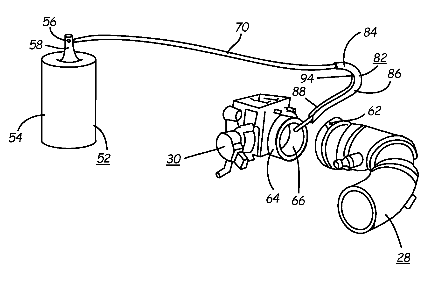
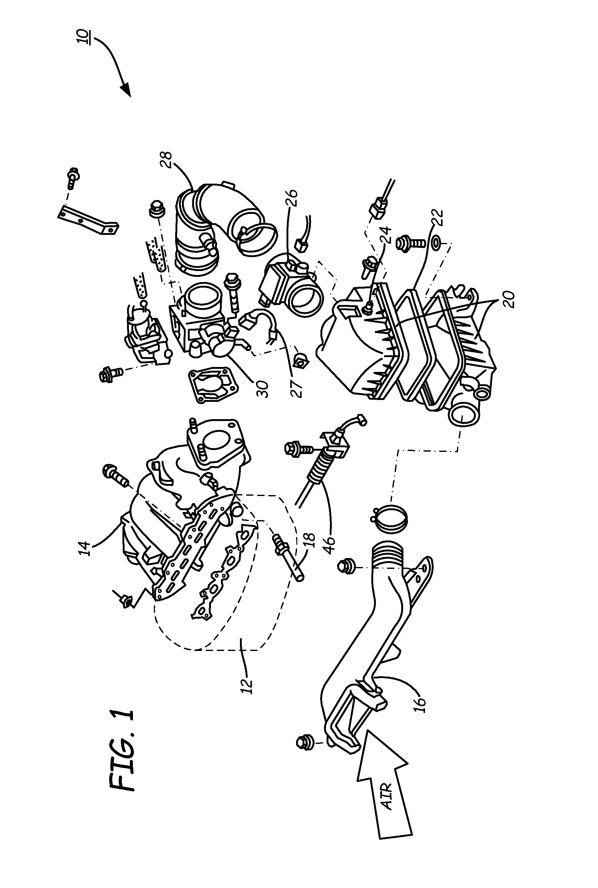
[0022]A delivery system for providing an atomized treatment agent to a specific internal location of a closed mechanical system like an internal combustion engine is provided by the invention. Such invention comprises a container for holding the atomized treatment agent under pressure as an aerosol or under compressed air, so that the atomized treatment agent is ejected in atomized form. The atomized treatment agent is delivered via a flexible, non-rigid conduit to the desired internal location inside the closed mechanical system. The free end of the conduit is inserted a predetermined distance into the closed mechanical system between, e.g., the ID / OD coupling joint between an air inlet hose and the cooperating inlet port collar of the mechanical part whose interior needs to be treated. The vacuum condition prevailing within the mechanical system will draw the atomized treatment agent into the internal mechanical system part, such as the fuel injectors, intake manifold, engine cyli...


PUM

PropertyMeasurementUnit
flexibleaaaaaaaaaa
lengthaaaaaaaaaa
mechanical energyaaaaaaaaaa

Abstract

The present invention provides a delivery system for providing an atomized treatment agent like a cleaner or lubricant to a specific internal location of a closed mechanical system like an internal combustion engine. The atomized treatment agent is delivered via a flexible, non-rigid conduit to the desired internal location of the engine between, e.g., the ID / OD coupling joint between the air inlet hose and the throttle body. A special conduit support guide, the end of which is inserted through the ID / OD coupling joint, provides the proper geometry for gently configuring the conduit to enter the ID / OD coupling joint without crimping and controlling the directional approach and distance of the conduit free end inside the engine.

Description

FIELD OF THE INVENTION[0001]This invention relates to the application of atomized spray products to difficult-to-reach locations. More specifically the invention uses a directional conduit guide support to direct the free end of a non-rigid conduit connected to the atomized spray container to a specific location within an enclosed mechanical system via a non-linear pathway, while preventing crimping of the conduit.BACKGROUND OF THE INVENTION[0002]An internal combustion engine burns a mixture of fuel and air to produce mechanical energy used to propel, e.g., an automobile. Pistons move up and down inside the engine's cylinders. As the pistons move down, intake valves located above the cylinders open, and fuel and air are sucked into the cylinders. The pistons then move back up inside the cylinders to compress the fuel-air mixture. Electric sparks produced by the vehicle's ignition system spark plugs ignite the fuel-air mixture. The resulting burning gases rapidly expand in volume to ...

Claims


Application Information

Patent Timeline
Patent Type & Authority Patents(United States)
IPC IPC(8): B08B9/00B01F23/10
CPCF01N2610/06F02M35/10209F02M35/10144F02B2077/045F02D9/1035F02M25/00F01N2610/00Y10T137/7058Y10T137/7051Y10T137/7043
Inventor HANSON, MATTHEW N.FANDREI, PHILIP F.
Owner AUTO MARK
Why Eureka
Try Eureka