Converter arrangement comprising movable contacts, but immovable converter assembly

a technology of immovable contacts and converter assemblies, applied in the direction of motor/generator/converter stoppers, dynamo-electric converter control, transportation and packaging, etc., can solve the disadvantage of ep 2 387 141 a1, inability to separate isolation switches, and become unnecessary, etc., to achieve simple, efficient, reliable and cost-effective

Active Publication Date: 2018-12-11
SIEMENS MOBILITY GMBH
View PDF15 Cites 0 Cited by
  • Summary
  • Abstract
  • Description
  • Claims
  • Application Information

AI Technical Summary

Benefits of technology

[0010]The object of the present invention consists of creating options by means of which, in a simple, efficient, reliable and cost-effective manner, an electrical disconnection of the converter assembly from the lines of the first network can be achieved.

Problems solved by technology

This means that independent isolation switches, which are present in the prior art in addition to the plug-in connections, become unnecessary.
The solution of EP 2 387 141 A1 is disadvantageous however because the entire mass of the converter assembly must be moved.
This is especially disadvantageous if the basic structure, and with it the converter assembly, is subjected to mechanical shock and shaking stresses and / or vibrations.

Method used


Image

  • Converter arrangement comprising movable contacts, but immovable converter assembly
  • Converter arrangement comprising movable contacts, but immovable converter assembly
  • Converter arrangement comprising movable contacts, but immovable converter assembly

Examples


Embodiment Construction

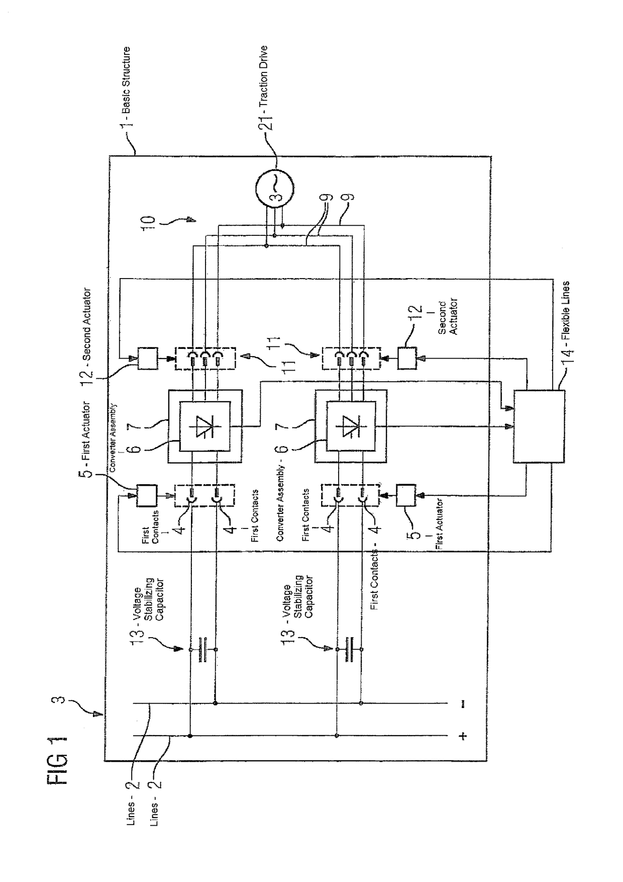
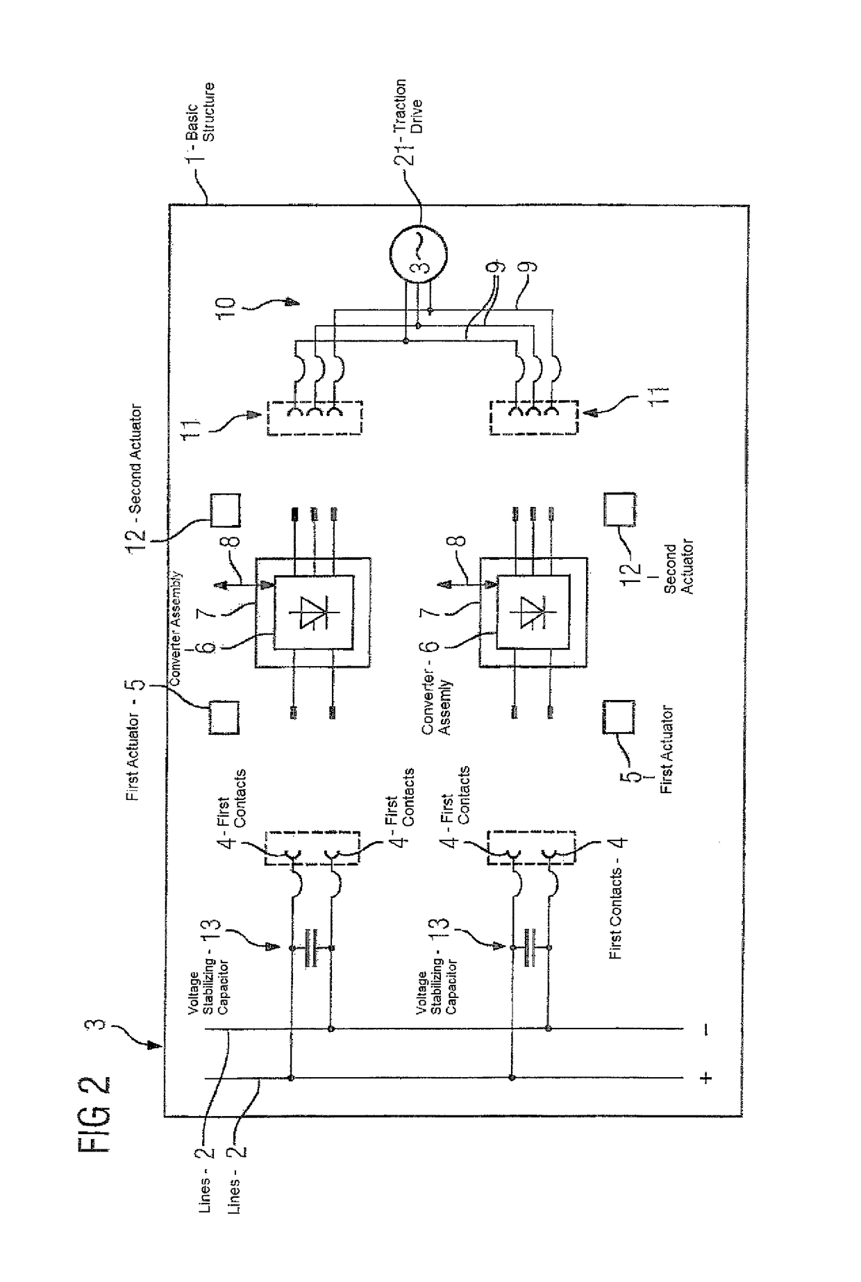
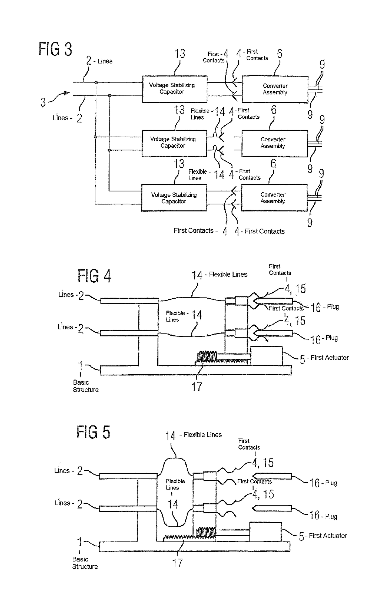
[0045]In accordance with FIG. 1 and FIG. 2, a converter arrangement has a basic structure 1. Arranged on the basic structure 1 are lines 2 of a first electrical network 3. The first network 3 can in particular be a DC voltage network. The lines 2 of a first network 3 can in particular be arranged in a fixed location on the basic structure 1.

[0046]Also arranged on the basic structure 1 is a plurality of first contacts 4. The first contacts 4 are able to be transferred by means of a first actuator 5 from a first connection position into a first release position. FIG. 1 shows the first contacts 4 in the first connection position, FIG. 2 shows them in the first release position.

[0047]When the first contacts 4 are located in the first release position, a converter assembly 6 is able to be fastened in a receptacle 7 of the basic structure 1 and is also able to be removed from it again. This is indicated in FIG. 2 by a double-ended arrow 8. The converter assembly 6 is at least embodied as ...


PUM


Abstract

A converter arrangement includes a basic structure having a receptacle, a first electrical network including lines arranged on the basic structure, a plurality of first contacts arranged on the basic structure and movable via a first actuator from a first connection position into a first release position, and a converter assembly securable in the first release position as a unit in a fixed location in the receptacle of the basic structure and removable from the receptacle. The converter assembly is electrically connected to the lines of the first electrical network when the first contacts assume the first connection position, and electrically disconnected from the lines of the first network when the first contacts assume the first release position. The receptacle of the basic structure is immobile when the first contacts move from the first connection position into the first release position.

Description

CROSS-REFERENCES TO RELATED APPLICATIONS[0001]This application is the U.S. National Stage of International Application No. PCT / EP2015 / 079045, filed Dec. 9, 2015, which designated the United States and has been published as International Publication No. WO 2016 / 116213 A1 which claims the priority of European Patent Application, Serial No. 15151795.0, filed Jan. 20, 2015, pursuant to 35 U.S.C. 119(a)-(d).BACKGROUND OF THE INVENTION[0002]The present invention is based on a converter arrangement,[0003]wherein the converter arrangement has a basic structure,[0004]wherein lines of a first electrical network are arranged on the basic structure.[0005]High-power converters are frequently constructed in a redundant arrangement for reasons of availability. This is also—but not only—true for example in the railroad field. In the case of a redundant structure the converter system consists of a number of individual converter assemblies.[0006]In the event of a malfunction of an individual converte...

Claims


Application Information

Patent Timeline
Patent Type & Authority Patents(United States)
IPC IPC(8): H02P3/00H02J4/00B60R16/03H02M7/00H02P27/04H01H31/32
CPCH02M7/003B60R16/03H02P27/04H02J4/00H01H31/32
Inventor NAGEL, ANDREASPONATH, HARALD
Owner SIEMENS MOBILITY GMBH
Why Eureka
Try Eureka