Sensor assembly and mounting method therefor

a technology of sensors and parts, applied in the field of sensors, can solve the problems of high complexity of assembly work, and achieve the effect of improving work efficiency, simple and reliable manner

Active Publication Date: 2020-10-01
NIFCO INC
View PDF0 Cites 0 Cited by
  • Summary
  • Abstract
  • Description
  • Claims
  • Application Information

AI Technical Summary

Benefits of technology

[0048]Since the jig serves as a means for pressing the vibrating member and a means for thermosetting the thermosetting bonding agent. the work efficiency is improved.
[0049]The present invention thus provides a sensor part provided with a vibrating member that can be mounted to a target member in a both simple and reliable manner without forming a hole in the target member.

Problems solved by technology

However, according to the sensor disclosed in Patent Document 1, the vibrating member and a case for protecting the vibrating member are required to be individually positioned and attached to the back side of the bumper, and components such as the circuit board for controlling the vibrating member are required to be attached to the vehicle body or the bumper so that the assembly work is highly complex.

Method used


Image

  • Sensor assembly and mounting method therefor
  • Sensor assembly and mounting method therefor
  • Sensor assembly and mounting method therefor

Examples


Embodiment Construction

)

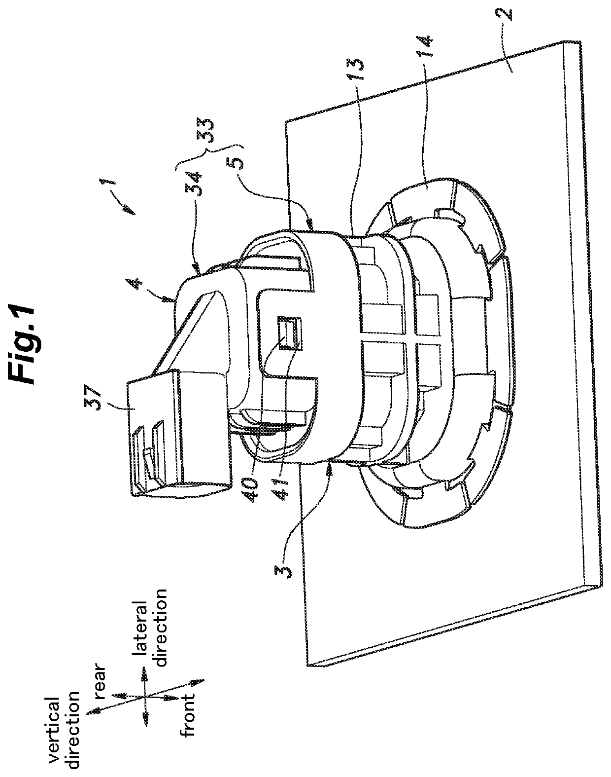
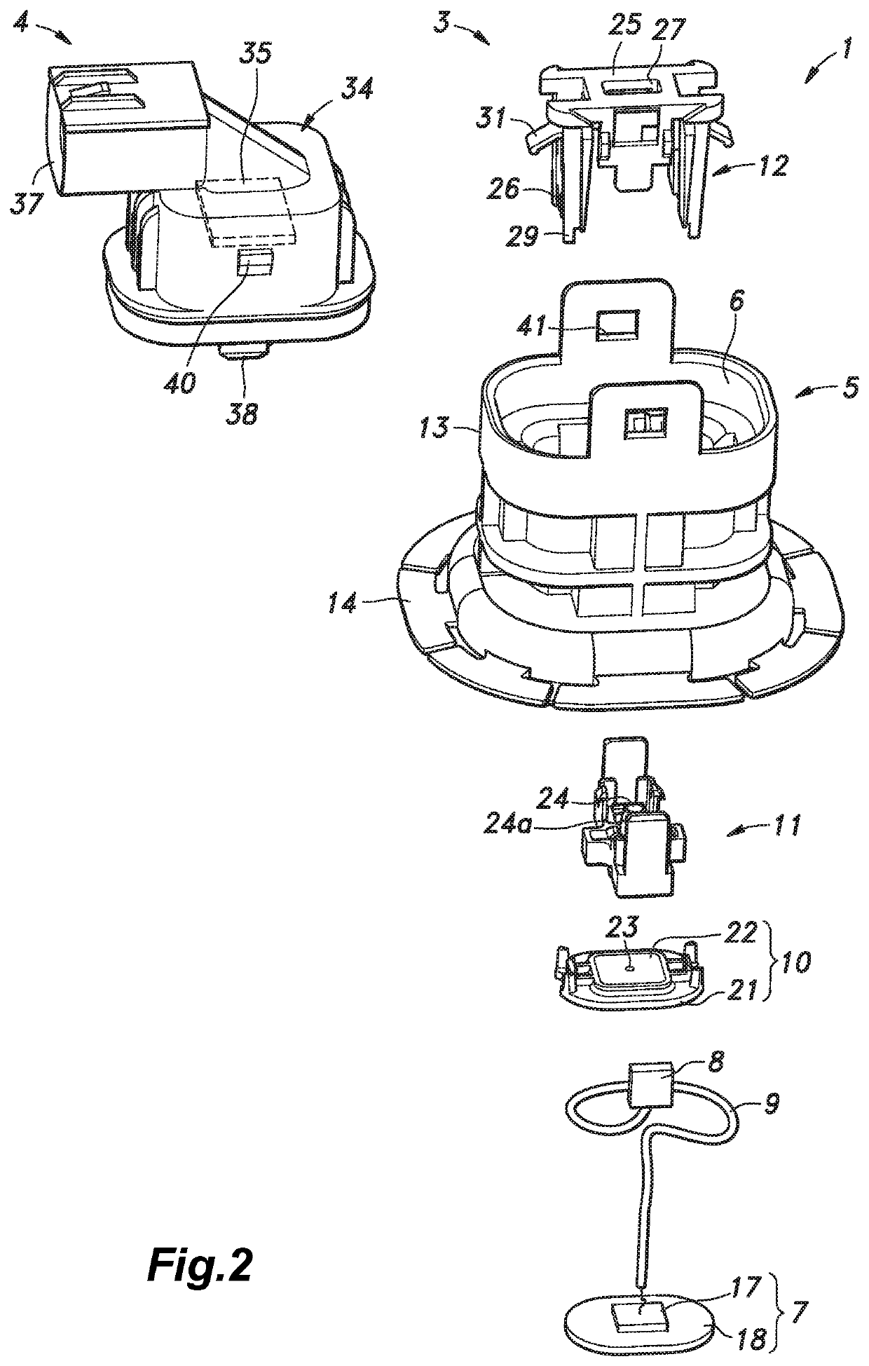
[0063]Embodiments of the present invention are described with reference to the appended drawings. FIGS. 1 and 2 are a perspective view and an exploded perspective view of a sensor part 1 according to a first embodiment of the present invention. The sensor part 1 includes a first assembly 3 fixed to a target member 2 such as a bumper of a vehicle and a second assembly 4 fixed to the first assembly 3. In the following description, the fore and aft direction, the vertical direction, and the lateral direction are defined as illustrated in the drawings. When the target member 2 is a front bumper and the sensor part 1 is mounted so as to face forward, the vertical direction in the description substantially coincides with the longitudinal direction of the vehicle. The target member 2 may consist of other types of members, and the sensor part 1 may be mounted so as to face the rear or lateral side of the vehicle.

[0064]The first assembly 3 includes a tubular first case 5 configured to be fi...


PUM


Abstract

Provided is a sensor part having a vibrating member and a mounting method therefor that allows the sensor part to be mounted to a target member such as a bumper in a simple, efficient and reliable manner. The sensor part includes a first assembly (3) including a tubular first case (5), a vibrating member (7) temporarily retained by the first case, and a pressing member (12) slidably supported in the first case, and a second assembly (4) including a second case (34) to be connected to the first case, and a circuit board (35) for controlling the vibrating member. After the first case is fixed to the target member, the pressing member is pushed so as to release the vibrating member from the temporal retention, and press the vibrating member against the target member.

Description

CROSS-REFERENCE TO RELATED APPLICATIONS[0001]This application is a U.S. National Phase Application of PCT / JP2018 / 046768, filed Dec. 19, 2018, which claims the benefit of priority to Japanese Patent Application No. 2017-248466, filed Dec. 25, 2017. The entire content of these applications is hereby expressly incorporated by reference.TECHNICAL FIELD[0002]The present disclosure relates to a sensor part having a vibrating member to be fixed to a bumper or any other member of a vehicle, and a mounting method therefor.BACKGROUND ART[0003]A sensor may be attached to the vehicle for the purpose of driving assistance or autonomous driving of the vehicle. An ultrasonic sensor attached to a bumper or the like detects an obstacle or the like by causing a vibrating member to generate an ultrasonic wave and detecting a reflected wave. A hole may be made in the bumper so that the vibrating member may be fitted in the hole, and associated component parts may be placed on the back side of the bumpe...

Claims


Application Information

Patent Timeline
Patent Type & Authority Applications(United States)
IPC IPC(8): G01S7/521F16B5/07G01S15/93G01S15/931
CPCG01S7/521G01S15/93F16B5/07B60R19/48G01S15/931G01S2015/938
Inventor OCHIAI, HIROSHIIZUME, TOMOHARU
Owner NIFCO INC
Why Eureka
Try Eureka