
Driving device for liquid discharging head, liquid discharging apparatus, and ink jet recording apparatus

a technology of liquid discharge head and driving device, which is applied in the direction of printing, spray nozzles, other printing apparatus, etc., can solve the problems of sacrificing discharge efficiency, image quality deterioration, and sacrificing the accuracy of landing position

Active Publication Date: 2014-01-21
FUJIFILM CORP
View PDF10 Cites 1 Cited by
  • Summary
  • Abstract
  • Description
  • Claims
  • Application Information

AI Technical Summary

Benefits of technology

This approach effectively suppresses satellite droplet formation, ensuring high-efficiency discharge and maintaining landing accuracy, thereby achieving desired dot shapes and image quality.

Problems solved by technology

By using the driving waveform designed as above, many of the shapes of liquid droplets during flight are disordered, whereby the image quality deteriorates.
However, in the former case, it is necessary to sacrifice the discharge efficiency, and, in the latter case, it is necessary to sacrifice the accuracy of the landing position.
However, there is concern that a satellite liquid droplet integrating with the main liquid droplet late is generated depending on the type of ink and differences in the discharge characteristics of heads.
Meanwhile, the reverberation of the meniscus remains, and accordingly, there is concern that the discharge of the main liquid droplet is affected by a successive driving waveform.

Method used


Image

  • Driving device for liquid discharging head, liquid discharging apparatus, and ink jet recording apparatus
  • Driving device for liquid discharging head, liquid discharging apparatus, and ink jet recording apparatus
  • Driving device for liquid discharging head, liquid discharging apparatus, and ink jet recording apparatus

Examples


modified examples

Modified Example 1

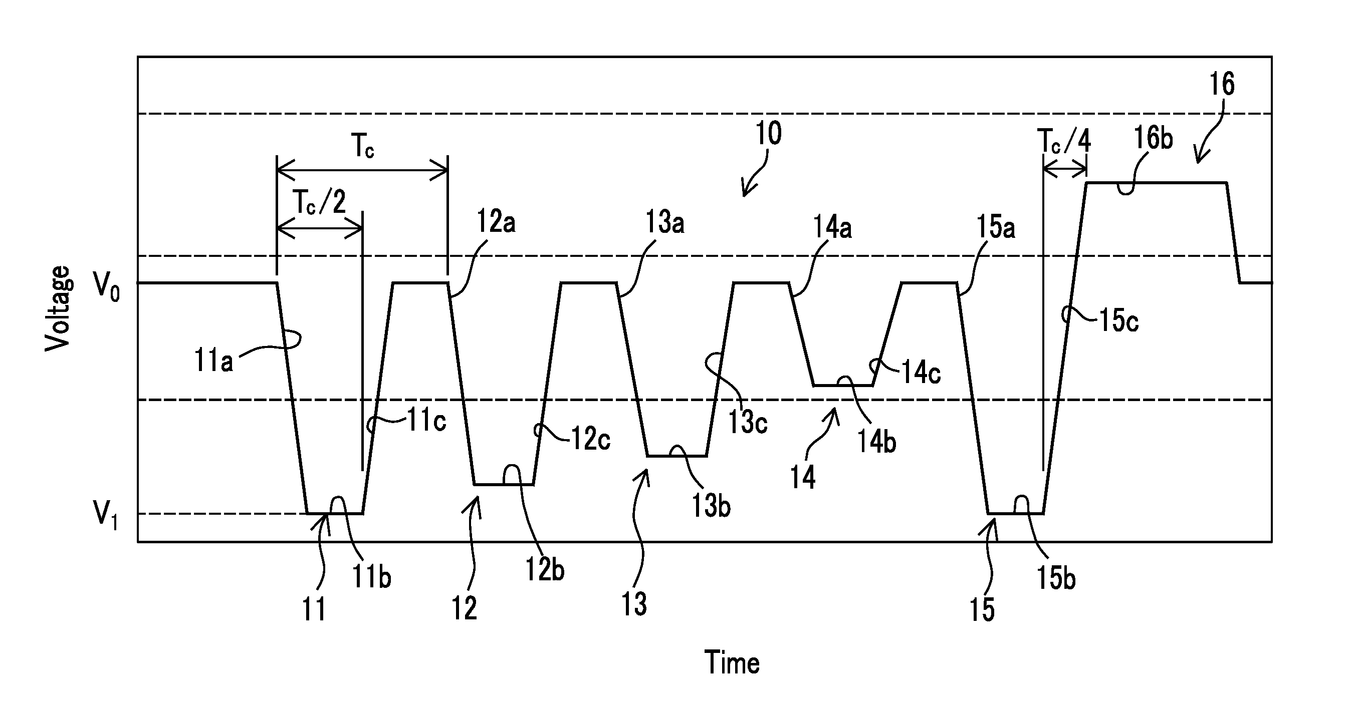
[0088]Next, modified examples of the above-described driving waveform will be described. FIG. 8 is a waveform diagram that illustrates another form of the driving waveform 10 illustrated in FIG. 1.

[0089]The driving waveform 20 illustrated in FIG. 8 is acquired by inverting the logic of the driving waveform 10 illustrated in FIG. 1. In other words, the driving waveform 20 causes the pressure chamber to expand in the rising waveform portions (first signal elements 21a, 22a, 23a, 24a, and 25a) of the first pulse 21 to the fifth pulse and causes the pressure chamber to contract in the falling waveform portions (third signal elements 21c, 22c, 23c, 24c, and 25c).

[0090]In other words, the driving waveform 10 (10A and 10B) illustrated in FIG. 1 (FIGS. 4 and 6) and the driving waveform 20 illustrated in FIG. 8 have the relation in which “rising” and “falling” of the pulses 11 to 15 and the pulses 21 to 25 are reversed.

[0091]In other words, as a common concept of the “falli...

modified example 2

[0094]FIG. 9 is a waveform diagram that illustrates a driving waveform acquired by excluding the reverberation suppressing pulse 16 from the driving waveform 10 illustrated in FIG. 1. The rising time of the final pulse 15 of the driving waveform 10, in which the reverberation suppressing pulse 16 is excluded, illustrated in FIG. 9 is a time until the electric potential changes to the reference electric potential V0 from the electric potential V5 of the second signal element 15b of the final pulse 15.

[0095]According to such a configuration, although it is difficult to suppress the reverberation of the meniscus, the generation of a satellite liquid droplet can be prevented by locating a main liquid droplet and the satellite liquid droplet during flight to be close to each other. In addition, the same advantages can be acquired by inverting the logic of the driving waveform 10 illustrated in FIG. 9 as illustrated in FIG. 8.

[0096]Pulse Width and Pulse Interval of Discharge Pulse

[0097]FI...


PUM


Abstract

Present invention provide a driving device of a liquid discharging head, a liquid discharging apparatus, and an ink jet recording apparatus that are capable of realizing a desired dot shape by suppressing the generation of the meniscus without sacrificing the discharge efficiency or the landing accuracy. According to the present invention, in a case where discharging is performed a plurality of times in one recording period, and one pixel is recorded by using a plurality of droplets, by configuring the wave height change time of a rear-end side wave height change part of the final pulse of a plurality of discharge pulses to be equal to or longer than a quarter of the resonant period Tc and configuring the pulse width of the plurality of discharge pulses to be a half of the resonant period Tc.

Description

BACKGROUND OF THE INVENTION[0001]1. Field of the Invention[0002]The present invention relates to a driving device that supplies a driving signal used for discharging liquid droplets from a nozzle of a liquid discharging head that is represented by an ink jet head and a liquid discharging apparatus and an ink jet recording apparatus that use the driving device.[0003]2. Description of the Related Art[0004]In ink jet recording apparatuses, in order to form images having a high quality, the shape of each dot that configures an image is required to be a perfect circle. Accordingly, a satellite liquid droplet must be prevented from landing at a position away from a landing position of a main liquid droplet. In order to prevent the generation of the satellite liquid droplet, a method in which a resonant period (Helmholtz natural oscillation period) is used in a driving waveform or a method that is based on a combination of consecutive pulses is proposed.[0005]In JP3241352B, an ink jet reco...

Claims


Application Information

Patent Timeline
Patent Type & Authority Patents(United States)
IPC IPC(8): B41J29/38
CPCB41J2/04516B41J2/04581B41J2/04591B41J2/04588B41J2/04595B41J2/04596
Inventor NISHIKAWA, BAKU
Owner FUJIFILM CORP
Learn More