
Unmanned aerial vehicle take-off and landing charging equipment

A technology for charging equipment and unmanned aerial vehicles, applied in the field of unmanned aerial vehicles, can solve the problems of tilting and overturning of unmanned aerial vehicles, failure of storage and charging of unmanned aerial vehicles, without considering the stability of machine feet, etc., and meet the requirements of high landing accuracy. , The effect of lowering the landing accuracy requirement and simple structure

Active Publication Date: 2021-07-23
GUANGDONG UNIV OF TECH
View PDF6 Cites 2 Cited by
  • Summary
  • Abstract
  • Description
  • Claims
  • Application Information

AI Technical Summary

Problems solved by technology

For example, Chinese patent CN209274922U discloses an automatic charging station for unmanned aerial vehicles, including a photovoltaic panel and a charging platform. There are two photovoltaic panels, which are connected to the charging platform through opening and closing devices respectively; , a charger, a charging sensor and an apron, which can realize the automatic charging of the UAV through the linear reciprocating mechanism of the opening and closing device, but it does not consider the stability of the machine feet, and it is easy to cause the UAV to tilt and overturn fall
In addition, the design schemes of some platforms require the landing accuracy of the drone to be very high. When the landing position and angle of the drone are inaccurate, it is easy to cause the failure of the storage and charging of the drone.

Method used


Image

  • Unmanned aerial vehicle take-off and landing charging equipment
  • Unmanned aerial vehicle take-off and landing charging equipment
  • Unmanned aerial vehicle take-off and landing charging equipment

Examples


Embodiment 1

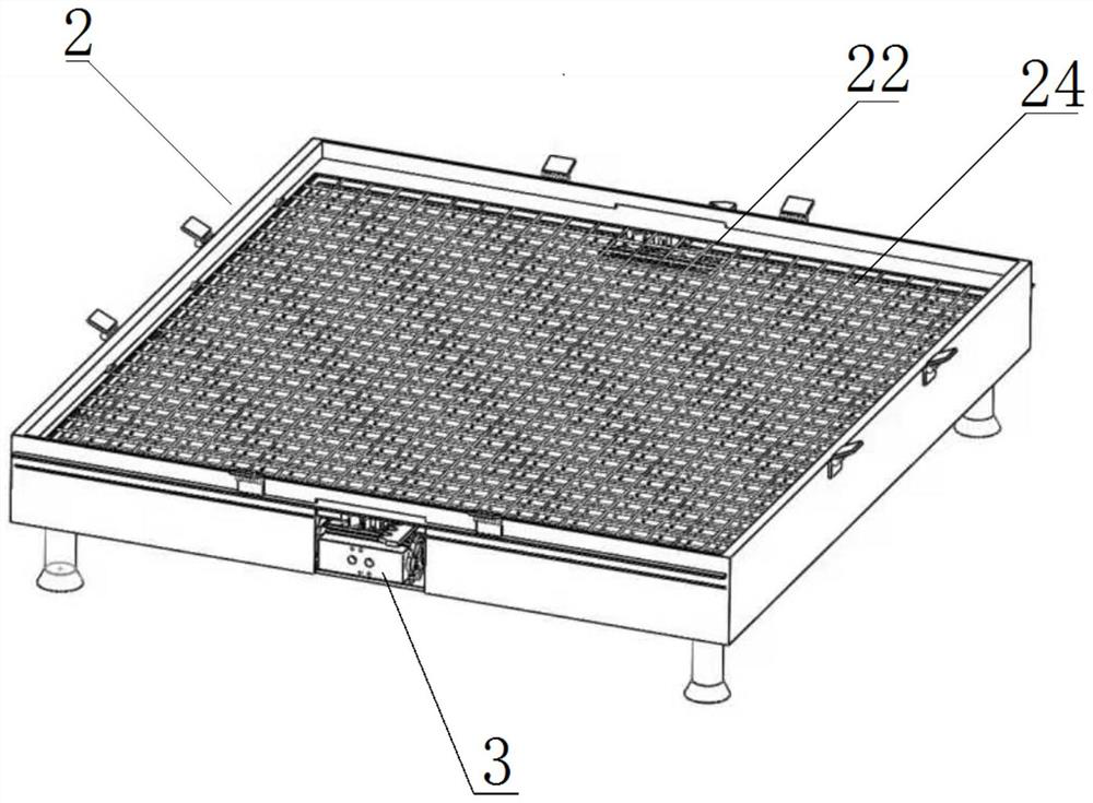
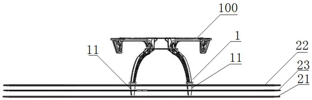
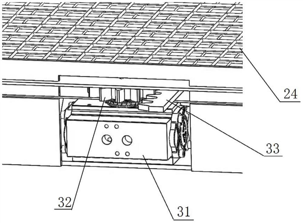
[0023] like figure 1 As shown, it is a drum-off and landing charging apparatus, including a charging platform 2, a control system, and a vertical charging frame for mounted on the drone 100, and the charging platform 2 includes a bottom plate 23 and a first side of the bottom plate 23. The first grid 22 and the second grid plate 23, the first grid plate 22 and the second grid plate 23 are parallel to each other and there is a spacing, and the bottom plate 23 is also provided with a charging device, and both ends of the charging device respectively and the first grid, respectively. The grid plate 22 and the second grid plate 23 are connected, and each of the first grid plates 22 and the second grid plate 23 are conducted and insulated from each other, and there are several one on the first grid plate 22 and the second grid plate 23. A relative to the set grid hole 24, the upright charge frame is provided with a grille hole 24 that can sequentially pass through the first grid plate ...

Embodiment 2

[0029] In this embodiment, in the first embodiment, in the present embodiment, in the present embodiment, the charging platform 2 is also provided with a folded platform outer cover 4, and the platform outer cover 4 is hinged on the four sides of the bottom plate 23. The solar panel 5 is formed on one side of the first grid 4 22 which is formed in a case where the solar panel 5 is formed. This embodiment is designed to be open, and the solar panel 5 is laid on the open box wall; when the weather is good, the sun is sufficient, the storage tank of the charging platform 2 opens, The battery in the drone charging platform 2 is charged by the solar conversion charging circuit. After the rainy weather, or after the drone 100 is landed, the box can be closed into a sealed structure to protect the drone 100 is not eroded by the wind and rain. This embodiment also integrates the solar charging function, which can be well applied to the occasion of the wild in the field. Thereby realizing ...


PUM


Abstract

The invention provides unmanned aerial vehicle take-off and landing charging equipment. The unmanned aerial vehicle take-off and landing charging equipment comprises a charging platform, a control system and a take-off and landing charging frame used for being installed on an unmanned aerial vehicle, the charging platform comprises a bottom plate, a first grating plate and a second grating plate, the first grating plate and the second grating plate are located above the bottom plate, a charging device is further arranged on the bottom plate, the positive electrode and the negative electrode of the charging device are connected with the first grating plate and the second grating plate correspondingly, charging feet are arranged on the take-off and landing charging frame, a driving mechanism is further arranged on the bottom plate, the driving mechanism drives the grating plates to move horizontally so as to clamp the charging feet for charging, and the control system is connected with the charging device and the driving mechanism. Through an innovative design of the net-shaped grid type landing locking device, the charging feet can be firmly locked as long as vehicle feet fall within the range of the grid cavity, then stable charging is conducted, and the success rate of autonomous landing, storage and charging of the unmanned aerial vehicle is increased.

Description

Technical field [0001] The present invention relates to the field of drone, and more particularly to a drone take-off and landing charging device. Background technique [0002] With the gradual development of drone technology, drone applications are increasingly wide, such as high-altitude, fire rescue, air inspection and other industries. At present, the civil engineering is more power-driven, and its maximum disadvantage is that the battery life is short and cannot be applied to applications where there is a high demand for battery life. In order to improve the endurance of the drone, many programs are proposed, such as the use of fuel engine instead of electric, or use fuel cell hydrogen energy, but these ways to improve endurance are either complex, not suitable for civilians, either technology is not mature. High cost; at the same time in some field works, such as power line inspections, most of the environment of drone operations is the deep forest of wild smoke, and operat...

Claims


Application Information

Patent Timeline
Patent Type & Authority Applications(China)
IPC IPC(8): B60L53/30B60L53/14
CPCB60L53/30B60L53/14B60L2200/10B64U50/19Y02T10/70Y02T10/7072Y02T90/12Y02T90/14
Inventor 陈元电陈帅文林镇标刘如泽周梓斌崔珩陈镇涛
Owner GUANGDONG UNIV OF TECH
Learn More