
Liquid jetting apparatus

Active Publication Date: 2013-12-05
BROTHER KOGYO KK
View PDF1 Cites 1 Cited by
  • Summary
  • Abstract
  • Description
  • Claims
  • Application Information

AI Technical Summary

Benefits of technology

The present patent invention relates to a liquid jetting apparatus that uses a recording medium to remove foreign matters. The technical effect is that the use of the recording medium removes the foreign matters without affecting the accuracy of landing of liquid. The recording medium is electrically charged to attract the foreign matters and remove them from the apparatus. This eliminates the need for an exclusive member to remove the foreign matters and ensures the absence of any decrease in landing accuracy.

Problems solved by technology

In the technique described above, an exclusive member as the cleaning member is required, and thus there is a cost disadvantage.

Method used


Image

  • Liquid jetting apparatus
  • Liquid jetting apparatus
  • Liquid jetting apparatus

Examples


first embodiment

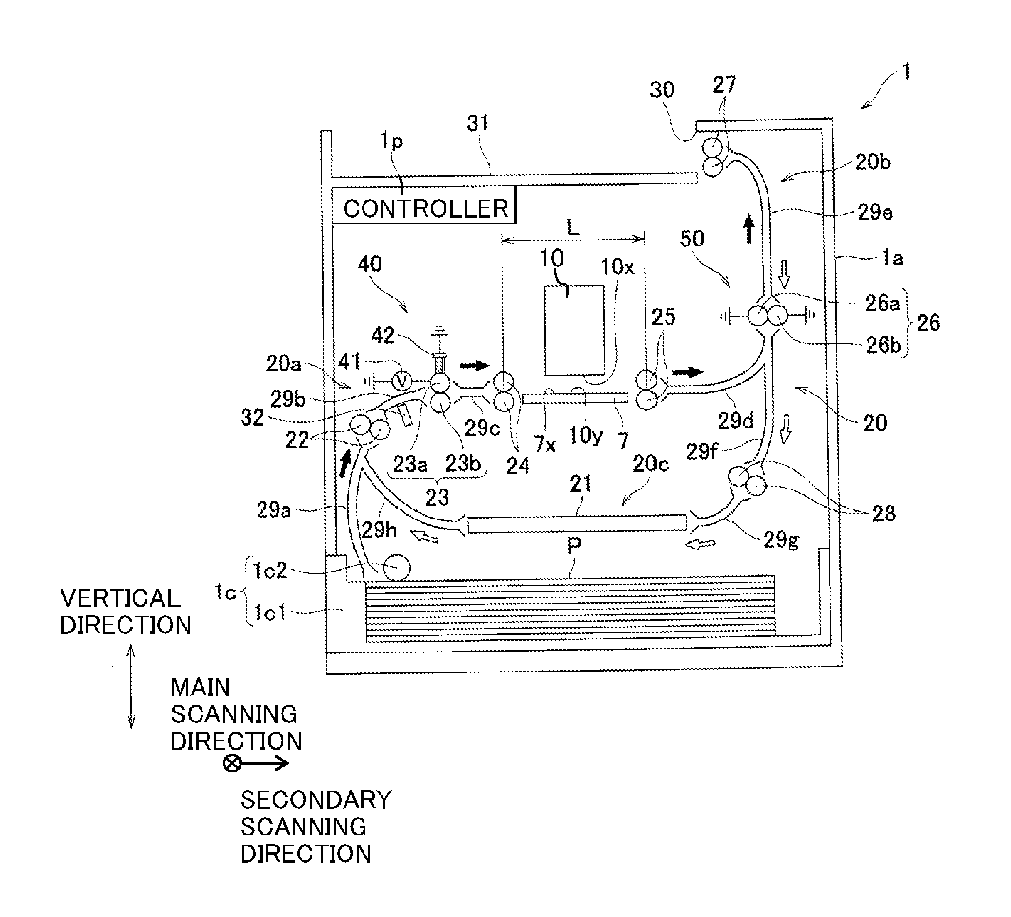
[0023]First, referring to FIG. 1, explanations will be made with respect to an overall construction of an ink-jet printer 1 according to the present teaching.

[0024]The printer 1 has a box-shaped casing 1a. A paper discharge section 31 is provided at the upper side of the top panel of the casing 1a. In the inner space of the casing 1a, a head 10, a platen 7 (an example of a support member), a paper sensor 32, a controller 1p (an example of a controller), a transport section 20, a paper feed unit 1c, and the like are accommodated. In the inner space of the casing 1a, a transport pass through which a paper sheet P is transported is formed from the paper feed unit 1c to the paper discharge section 31 along thick arrows shown in FIG. 1. Further, in the casing 1a, a cartridge (not shown) containing a black ink to be supplied to the head 10 is provided removably. The cartridge is connected to the head 10 via a tube etc., and the ink is supplied to the head 10.

[0025]The head 10 is a line he...

second embodiment

[0068]Subsequently, an explanation will be made about an ink-jet printer 201 according to the present teaching with reference to FIG. 9 and FIG. 10.

[0069]The structures of the charging section and the foreign substance elimination section in the printer 201 of the second embodiment are different from those in the printer 1 of the first embodiment. Other structures in the printer 201 are the same as those in the printer 1 of the first embodiment.

[0070]In the second embodiment, a charging section 240 is constructed of a pair of rollers 223, a sponge 241 (an example of the voltage applying section and a contact-separation member), a solenoid 243 (an example of the contact-separation mechanism), and the electricity removal brush 42 as shown in FIG. 9.

[0071]The pair of rollers 223 includes rollers 223a and 223b. Although illustrations are omitted in FIG. 9 and FIG. 10, a plurality of rollers 223a (an example of the charging member, the contact member and the rotating member) are provided...

third embodiment

[0084]Subsequently, an explanation will be made about an ink-jet printer 301 according to the present teaching with reference to FIG. 11 and FIGS. 12A and 12B.

[0085]The structure of the charging section in the printer 301 of the third embodiment is different from that of the printer 1 of the first embodiment. Other structures in the printer 301 are the same as those in the printer 1 of the first embodiment.

[0086]In the third embodiment, a charging section 340 is constructed of a pair of rollers 323, a power source 341 (an example of the voltage applying section), and a solenoid 343 (an example of the movement mechanism) as shown in FIG. 11.

[0087]The pair of rollers 323 includes rollers 323a (an example of the charging member, the contact member and the second roller) and a roller 323b (an example of the first roller). As shown in FIG. 12A, a plurality of rollers 323a are provided similar to the rollers 23a in the first embodiment (see FIG. 5A), and the plurality of rollers 323a are ...


PUM


Abstract

A liquid jetting apparatus includes: a jetting section having a plurality of jetting ports for jetting a liquid; a transport section configured to transport the recording medium along a transport pass having a facing area which faces the plurality of jetting ports; a charging section arranged on an upstream side of the facing area in a transport direction in which the recording medium is transported by the transport section, and configured to charge the recording medium; a charged-area determining section configured to determine a non-landing area, of the recording medium, in which the liquid jetted from the plurality of jetting ports is not landed in a case that the recording medium is disposed at the facing area, as a charged area; and a controller configured to control the charging section to charge the charged area determined by the charged-area determining section.

Description

CROSS REFERENCE TO RELATED APPLICATION[0001]The present application claims priority from Japanese Patent Application No. 2012-124496, filed on May 31, 2012, the disclosure of which is incorporated herein by reference in its entirety.BACKGROUND OF THE INVENTION[0002]1. Field of the Invention[0003]The present invention relates to a liquid jetting apparatus which jets a liquid to a recording medium.[0004]2. Description of the Related Art[0005]In the known technique, a cleaning member is transported in a state of being electrically charged in an image forming apparatus, and foreign matters in the apparatus is removed by being adsorbed to the cleaning member.[0006]In the technique described above, an exclusive member as the cleaning member is required, and thus there is a cost disadvantage.SUMMARY OF THE INVENTION[0007]Thus, the inventor of the present teaching has considered that foreign matters in a liquid jetting apparatus are removed by using a recording medium in the apparatus. As a...

Claims


Application Information

Patent Timeline
IPC IPC(8): B41J2/165
CPCB41J2/16535B41J11/0015
Inventor SAKANO, YUJI
Owner BROTHER KOGYO KK
Learn More