Liquid ejection apparatus
a liquid ejection and apparatus technology, applied in the direction of printing, other printing apparatus, etc., can solve the problems of degrading image quality, mist may merge into large ink droplets, and likely affect the air current surrounding, so as to suppress the adverse effect and improve the landing accuracy
- Summary
- Abstract
- Description
- Claims
- Application Information
AI Technical Summary
Benefits of technology
Problems solved by technology
Method used
Image

Examples
first embodiment
[0027]An ink jet printing apparatus according to a first embodiment of the present invention will be described.
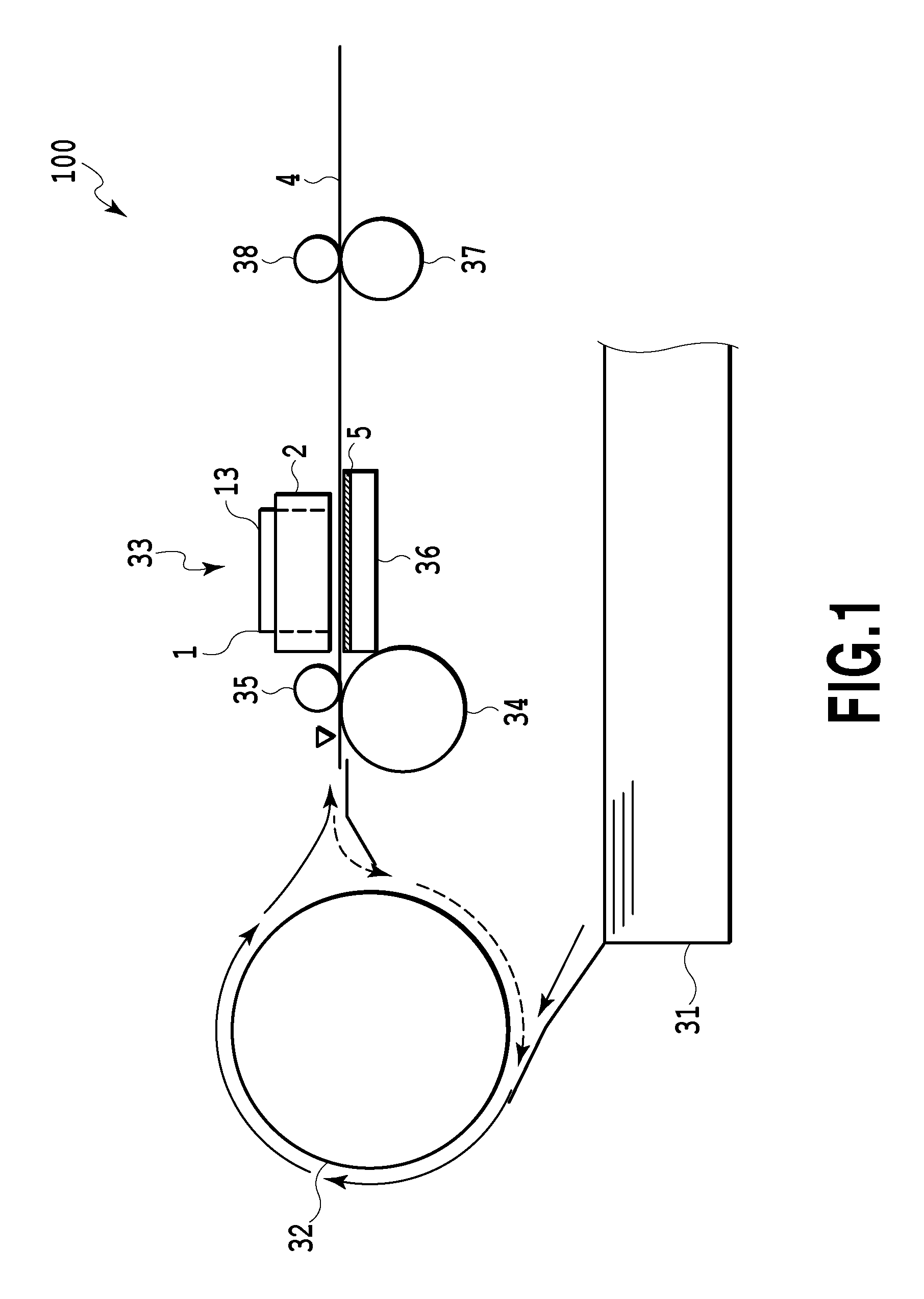
[0028]FIG. 1 shows a schematic cross-sectional view of an ink jet printing apparatus 100. FIG. 1 is a schematic side view of the ink jet printing apparatus 100 as seen from the side of the ink jet printing apparatus 100.
[0029]The inkjet printing apparatus 100 includes a sheet feeding cassette 31 and a U-turn conveying unit 32. Print media 4 that have not been printed are housed and stacked in the sheet feeding cassette 31. The U-turn conveying unit 32 is disposed on a downstream side of the print media in the sheet feeding cassette 31 in a conveying direction. The U-turn conveying unit 32 also has the function of a double-side inversion unit. The conveying direction of the print medium is hereinafter simply referred to as the conveying direction. Furthermore, an upstream direction and a downstream direction in the conveying direction of the print medium are hereinafter simp...
second embodiment
[0062]Now, an ink jet printing apparatus according to a second embodiment will be described. Components of the second embodiment similar to the corresponding components of the first embodiment are denoted by the same reference numerals in the figures and will not be described. Only differences from the first embodiment will be described.
[0063]In the first embodiment, the form has been described in which the present invention is applied to the serial scan ink jet printing apparatus performing printing while the print head 1 is moving along the main scanning direction. In contrast, in the second embodiment, the present invention is applied to a full line ink jet printing apparatus that uses a print head extending all over the print medium in the width direction thereof.
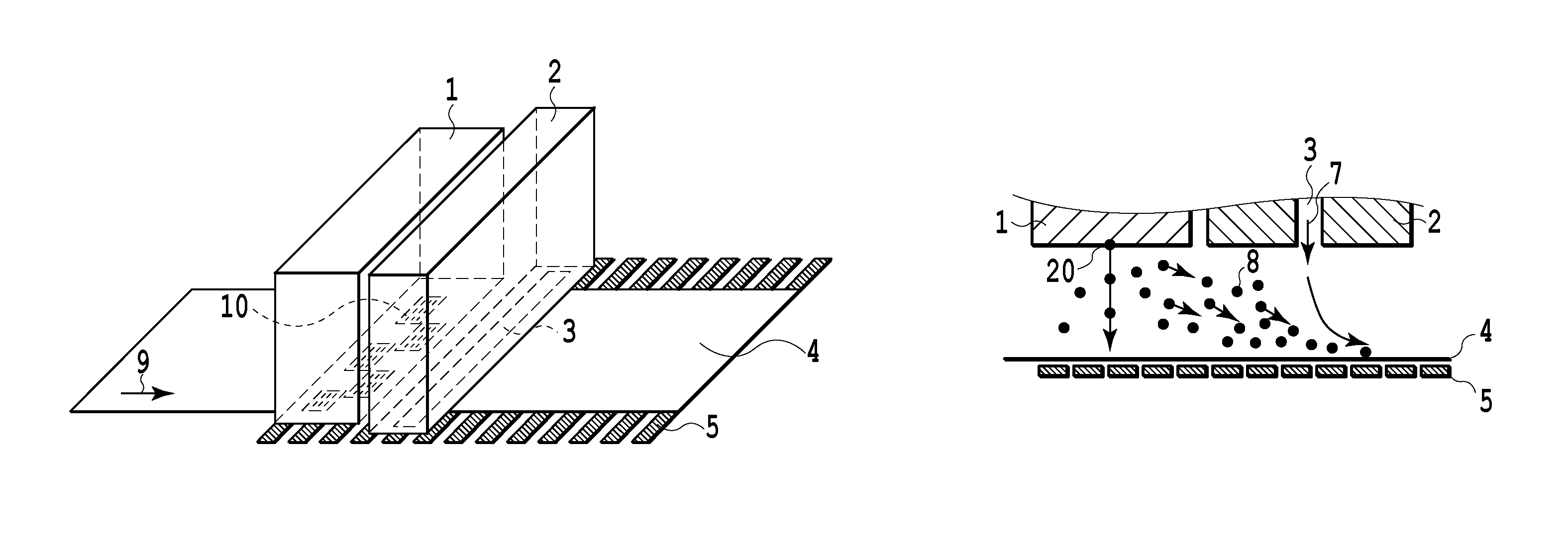
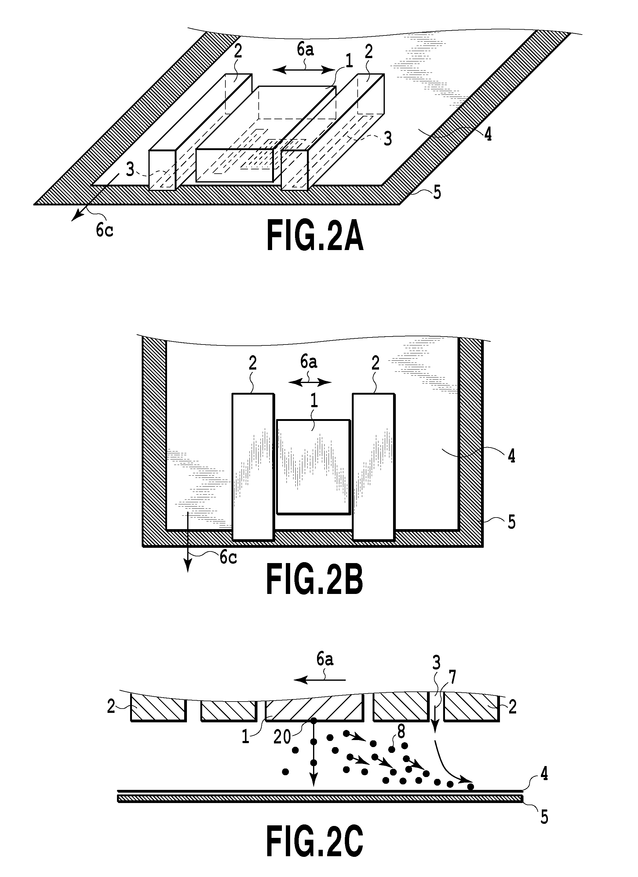
[0064]In the second embodiment, the print head 1 and the blowout mechanism 2 are disposed opposite the print medium 4 as is the case with the first embodiment. In the present embodiment, no scan is performed by the prin...
third embodiment
[0075]Now, an ink jet printing apparatus according to a third embodiment will be described. Components of the third embodiment similar to the corresponding components of the second embodiment are denoted by the same reference numerals in the figures and will not be described. Only differences from the second embodiment will be described.
[0076]In the first embodiment and the second embodiment, the electrode 5 is also disposed in the upstream area with respect to the conveying direction of the print head 1. In the first embodiment and the second embodiment, a portion of the electrode 5 is disposed in the area where the ink mist 8 is unlikely to be generated, and a voltage is applied to this portion. However, normally, at the upstream position with respect to the print head 1, the ink mist is unlikely to be generated. Thus, the voltage is applied to the electrode 5 at the position thereof where the ink mist is unlikely to be generated, and may thus be wastefully used. Consequently, mor...
PUM
 Abstract
Description
Claims
Application Information