
System and method for system integration test (SIT) planning

a system integration and test technology, applied in the field of system integration test (sit), can solve the problems of software system size and complexity, software developers compromising functionality, time to market, software product quality,

Inactive Publication Date: 2014-01-21
INT BUSINESS MASCH CORP
View PDF73 Cites 3 Cited by
  • Summary
  • Abstract
  • Description
  • Claims
  • Application Information

AI Technical Summary

Problems solved by technology

While software systems continue to grow in size and complexity, business demands continue to require shorter development cycles.
This has led software developers to compromise on functionality, time to market, and quality of software products.
Furthermore, the increased schedule pressures and limited availability of resources and skilled labor can lead to problems such as incomplete design of software products, inefficient testing, poor quality, high development and maintenance costs, and the like.
This may lead to poor customer satisfaction and a loss of market share for companies developing software.
Moreover, as the software development lifecycle proceeds from high level requirements / design review to, for example, system integration test (SIT), performance test and user acceptance test, costs for detecting and remedying software defects generally increases, e.g., exponentially.
Thus, two critical factors are not typically adequately addressed in the SIT approach: (1) system architecture (including connections and interactions); and (2) an ability to empirically determine the optimal allocation of effort across different testing focuses within the system integration testing (SIT) activity.
There are no industry wide models available to provide appropriate expected distributions of defects uncovered in System Integration Testing (SIT).
As a result, different testing focus areas that an effective SIT should include are rarely if ever distributed optimally.
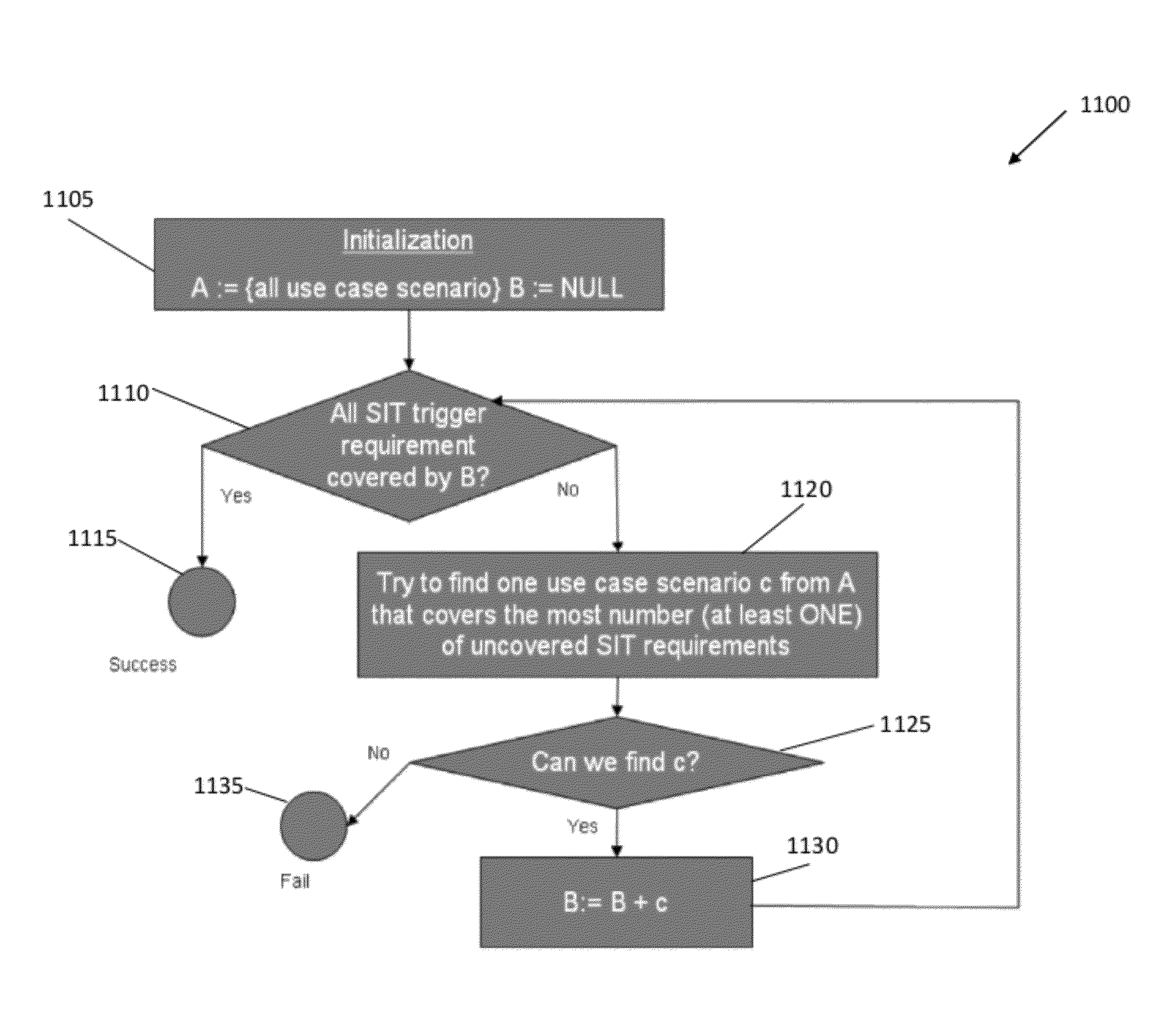
For example, many use cases actually walk through the same connection among systems / components with the same interface and data, which produces redundant test cases.
Therefore, the SIT phase of the software development life cycle tends to be one of the most expensive kinds of testing relative to the benefit received.

Method used


Image

  • System and method for system integration test (SIT) planning
  • System and method for system integration test (SIT) planning
  • System and method for system integration test (SIT) planning

Examples


Embodiment Construction

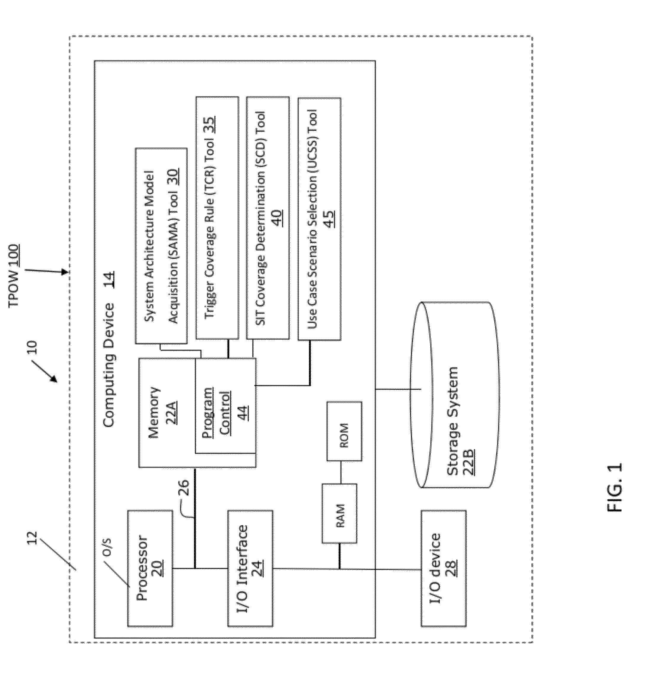
[0023]The present invention generally relates to system integration testing (SIT), and more particularly, to a system and method for SIT planning leveraging a system architecture model and defect reduction method (DRM) triggers. The present invention is operable to derive an optimized and achievable SIT allocation of effort strategy consistently and accurately across any system integration effort, regardless of size, complexity, or industry. The present invention incorporates elements of (1) the system architecture and (2) the defect reduction method (DRM) to optimize the distribution of test cases for SIT efforts.

[0024]Implementing the present invention enables a significant reduction of overall testing costs while simultaneously improving test quality, for example, for complex system integration clients. For example, the present invention provides appropriate expected defect distributions of SIT in order for an organization to effectively address such defects, e.g., optimize the d...


PUM


Abstract

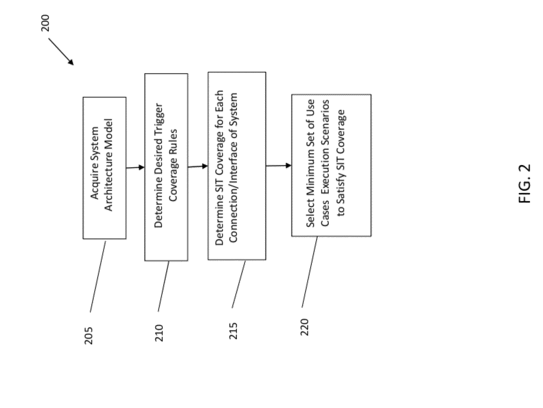
A method is implemented in a computer infrastructure having computer executable code tangibly embodied on a computer readable storage medium having programming instructions. The programming instructions are operable to receive a system architecture model of a system and receive trigger coverage rules. Additionally, the programming instructions are operable to determine system integration test (SIT) coverage for each connection and interface of the system architecture model and select a set of use cases execution scenarios to satisfy the SIT coverage.

Description

CROSS REFERENCE TO RELATED APPLICATIONS[0001]The present invention is a continuation application of U.S. application Ser. No. 12 / 558,375, filed on Sep. 11, 2009, and is related to U.S. application Ser. Nos. 12 / 558,327, filed on Sep. 11, 2009; 12 / 558,274, filed on Sep. 11, 2009; 12 / 558,260, filed on Sep. 11, 2009; and 12 / 558,147, filed on Sep. 11, 2009, the contents of which are incorporated by reference in their entireties herein.FIELD OF THE INVENTION[0002]The present invention generally relates to system integration testing (SIT), and more particularly, to a system and method for SIT planning leveraging a system architecture model and defect reduction method (DRM) triggers.BACKGROUND[0003]While software systems continue to grow in size and complexity, business demands continue to require shorter development cycles. This has led software developers to compromise on functionality, time to market, and quality of software products. Furthermore, the increased schedule pressures and lim...

Claims


Application Information

Patent Timeline
Patent Type & Authority Patents(United States)
IPC IPC(8): G06F9/45
CPCG06F11/3676A61B5/7275G16H50/30
Inventor BASSIN, KATHRYN A.KAGAN, STEVENLI, SHAO C.LI, ZHONG J.LIU, HE H.SKRABANEK, SUSAN E.TAN, HUA F.ZHU, JUN
Owner INT BUSINESS MASCH CORP
Learn More