Method for defect determination in fine concave-convex pattern and method for defect determination on patterned medium

a concave-convex pattern and defect determination technology, applied in the field of fine concave-convex pattern defect determination and method for defect determination on patterned medium, can solve the problems of complex analysis, deformation, peeling, etc., and achieve the effect of easy identification of defect types, enhanced yields, and contributing to process stability

Inactive Publication Date: 2014-01-28
HITACHI HIGH-TECH CORP
View PDF6 Cites 2 Cited by
  • Summary
  • Abstract
  • Description
  • Claims
  • Application Information

AI Technical Summary

Benefits of technology

[0012]In such defect determination, a conventional method, that is, the inspection of the shape of an object only with detected reflection light intensity by the scatterometry method, complicates the analysis, increases the inspection time by analysis or matching processing, and decreases the inspection / measurement accuracy.
[0014]It is an object of the present invention to easily identify a defect type on a sample where fine concave-convex patterns are formed, without increasing inspection time.
[0021]The invention makes it possible to easily identify a defect type on a sample where fine concave-convex patterns are formed, such as on a patterned medium, and contributes to the stability of processes and the enhancement of yields.

Problems solved by technology

In a manufacturing process, there are various types of defects such as pattern deformation, peeling, a dent, a scratch, and a particle on the disk.
Further, the acceptance or rejection of the product depends on a defective area on the disk.
On the other hand, if a similar defect occurs in an address determination pattern in a servo area, an entire data area determined by the address pattern can be unusable, which leads to a critical defect, so that the product is rejected.
In such defect determination, a conventional method, that is, the inspection of the shape of an object only with detected reflection light intensity by the scatterometry method, complicates the analysis, increases the inspection time by analysis or matching processing, and decreases the inspection / measurement accuracy.

Method used


Image

  • Method for defect determination in fine concave-convex pattern and method for defect determination on patterned medium
  • Method for defect determination in fine concave-convex pattern and method for defect determination on patterned medium
  • Method for defect determination in fine concave-convex pattern and method for defect determination on patterned medium

Examples


first embodiment

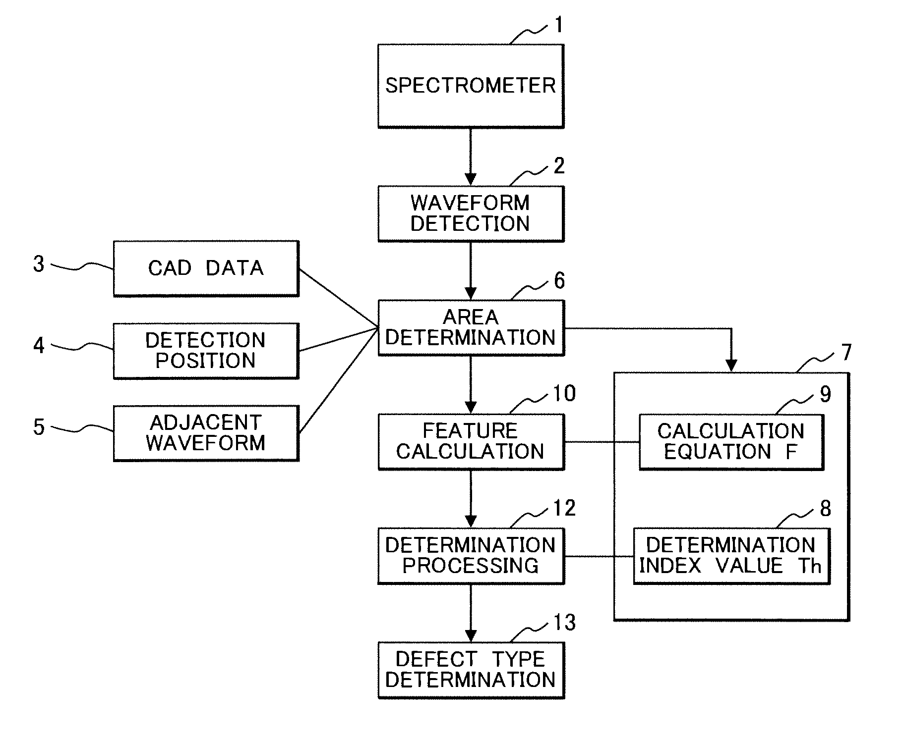
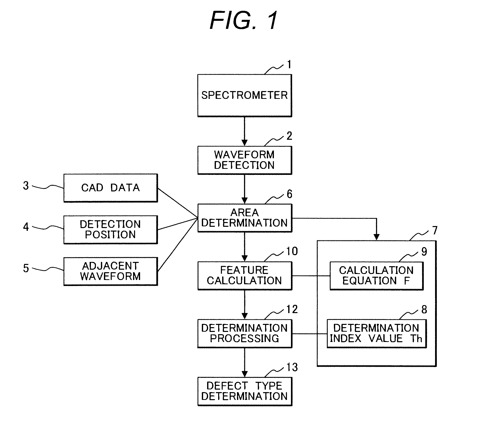
[0036]FIG. 1 shows a process flow of patterned media inspection according to the present invention.

[0037]A spectrometer 1 detects the spectral reflectance of a detection area on a patterned media disk to be inspected to perform waveform detection 2 as spectral waveform data. Then, based on a detection position 4 and CAD data 3 as media design information, area determination 6 is performed as to which area the detected waveform belongs to. The area refers to an area section such as a data area and a servo area determined by a pattern type on the disk. In the case where there is no alignment mark or the like necessary for positioning on the disk so that the detection position 4 is undetectable, the area determination 6 is performed in comparison with an adjacent waveform 5 associated with an area section detected beforehand.

[0038]Based on the result of the area determination 6, a calculation equation F 9 and a determination index value Th 8 corresponding to the determined area are sel...

second embodiment

[0063]FIG. 12 shows an example of another determination database table according to the invention. In area setting in the first embodiment, the data area is divided into, for example, three areas in the radial direction of the disk, that is, inner, middle, and outer periphery areas. This is because, due to the nature of the hard disk, the recording density is higher toward the inner periphery, so that the pattern density may also vary depending on the radial position. In this case, it is not necessary to calculate the coefficients of the calculation equation Fi independently in all areas, and interpolation may be performed between adjacent areas. Further, the number of divisions is not limited to three and may be more than three.

third embodiment

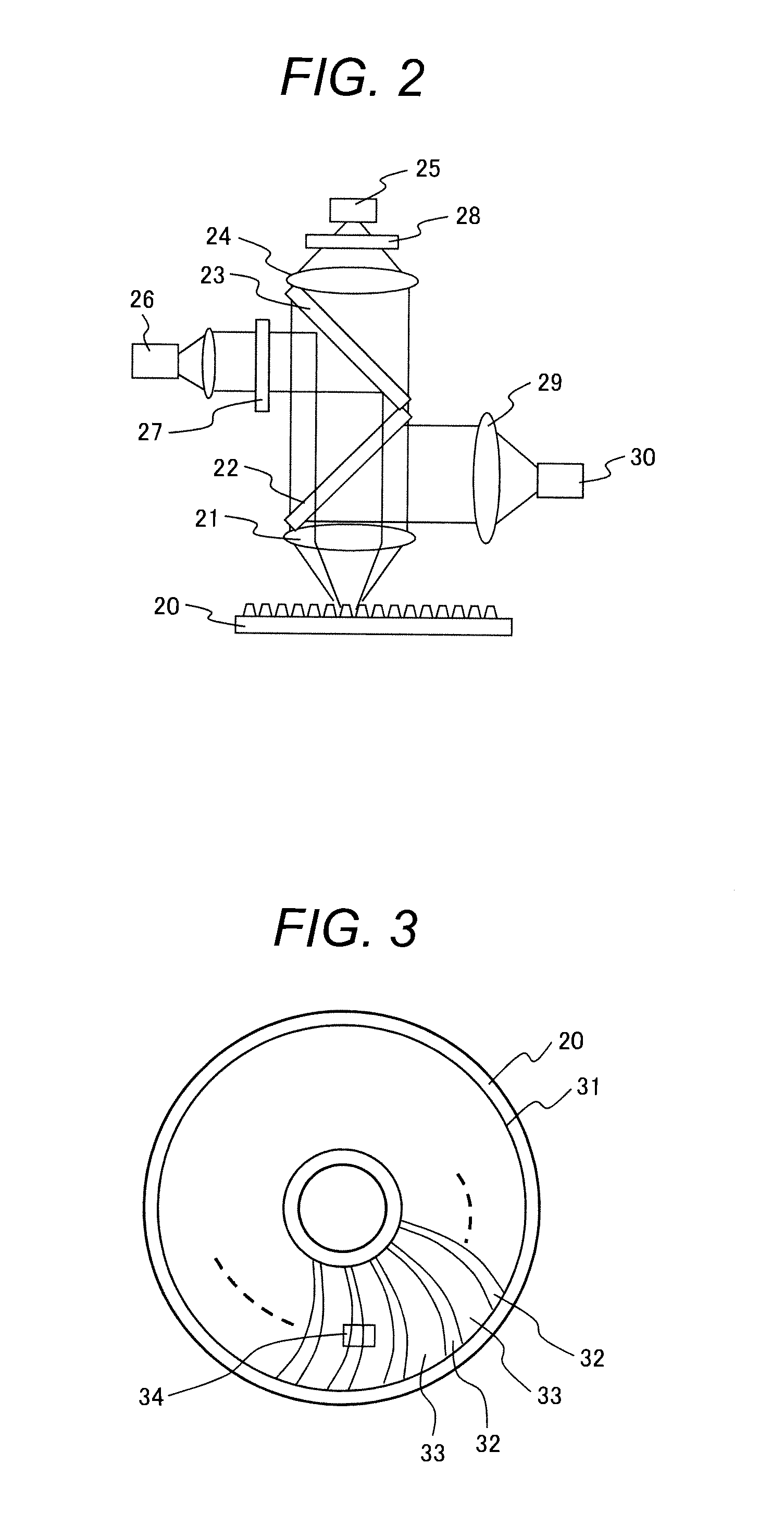
[0064]FIGS. 13A and 13B show another example of a determination database according to the invention. When a spectral waveform is detected by the spectrometer 1 according to the first embodiment, a waveform 70 of FIG. 13A detected by the light detector 25 and a defect image 71 of FIG. 13B captured by the camera 30 are associated together and stored in the database. This makes it possible to show the defect image 71 to a user as a defect image example after determination.


PUM

PropertyMeasurementUnit
wavelengthsaaaaaaaaaa
defect typeaaaaaaaaaa
areaaaaaaaaaaa

Abstract

In the inspection of a defect in a fine concave-convex pattern, a spectral waveform of a detection area of an inspection object is detected, area determination as to which area section determined by a pattern type of the inspection object the detection area belongs to is performed, a feature calculation equation and a determination index value which correspond to a determined area section and vary according to defect type is selected, feature calculation on the spectral waveform data in accordance with the selected feature calculation equation is performed, and a calculated feature value and the selected determination index value are compared to perform determination processing according to defect type.

Description

CLAIM OF PRIORITY[0001]The present application claims priority from Japanese patent application JP2009-128996 filed on May 28, 2009, the content of which is hereby incorporated by reference into this application.BACKGROUND OF THE INVENTION[0002]1. Field of the Invention[0003]The present invention relates to inspection of a product and a process for producing a concave-convex pattern shape such as on a hard disk medium, and to a technique for inspecting a defect, deformation, and dimension measurement of the pattern shape.[0004]2. Description of the Related Art[0005]In recent years, hard disks as recording media for use in computers have been increasing in capacity. For increases in the capacity of recording information, it is essential to increase the recording density of a disk. As a method for greatly increasing the recording density compared to conventional disk media, patterned media having patterns formed on the disk surface are showing great promise. To form patterned media, a...

Claims


Application Information

Patent Timeline
Patent Type & Authority Patents(United States)
IPC IPC(8): G01N21/00H01L21/66G01N21/956G01N21/95
CPCG11B5/82G01N21/956G01N21/95692G01N21/95607G11B5/855G01N21/9501H01L22/10
Inventor SASAZAWA, HIDEAKIHIROSE, TAKENORISERIKAWA, SHIGERU
Owner HITACHI HIGH-TECH CORP
Why Eureka
Try Eureka