Sign post system

a technology applied in the field of signs and posts, can solve the problems of damage to highway signs, signs or signs, delineators located at the side of the road for guidance and warning of passing motorists, and may occur damage, so as to achieve the effect of increasing the degree of relative twisting rotation

Inactive Publication Date: 2014-02-04
ADAPT EZE SAFETY PROD
View PDF43 Cites 12 Cited by
  • Summary
  • Abstract
  • Description
  • Claims
  • Application Information

AI Technical Summary

Problems solved by technology

Typically, damage may occur when the sign or signpost is struck by snow thrown by a snowplough or is struck by the snowplough blade itself.
For example, as stated by Shirley in his U.S. Pat. No. 4,205,472, which issued Jun. 3, 1980 for his Yieldable Delayed Action Roadway and Signing Apparatus, on vehicle roadways, particularly in areas where roadways are covered with snow for a part of the year, a continuing problem is the damage and destruction of highway signs and delineators situated at the side of the road for the guidance and warning of passing motorists.
Because of their proximity to the edge of the road they are subject to damage by weed mowers and snowploughs and occasionally by automobiles.
In the winter months when the roadways and adjacent areas are covered with snow it is quite easy for snowplough operators to accidentally damage or ruin signs at the side of the road.
They must remove enough snow to uncover the roadway and in doing so in deep snow they are likely to remove snow from too wide a path and run into the roadside marker.
Mowers also do accidental damage frequently.
However, these ideas may not have been widely adopted because the devices are almost as susceptible to injury as the original posts.
Although they theoretically have resilient properties and can spring back to their original position after having been knocked over, in practice the snowplough can completely uproot such posts or sever them or otherwise irreparably damage them.

Method used


Image

  • Sign post system
  • Sign post system
  • Sign post system

Examples


Embodiment Construction

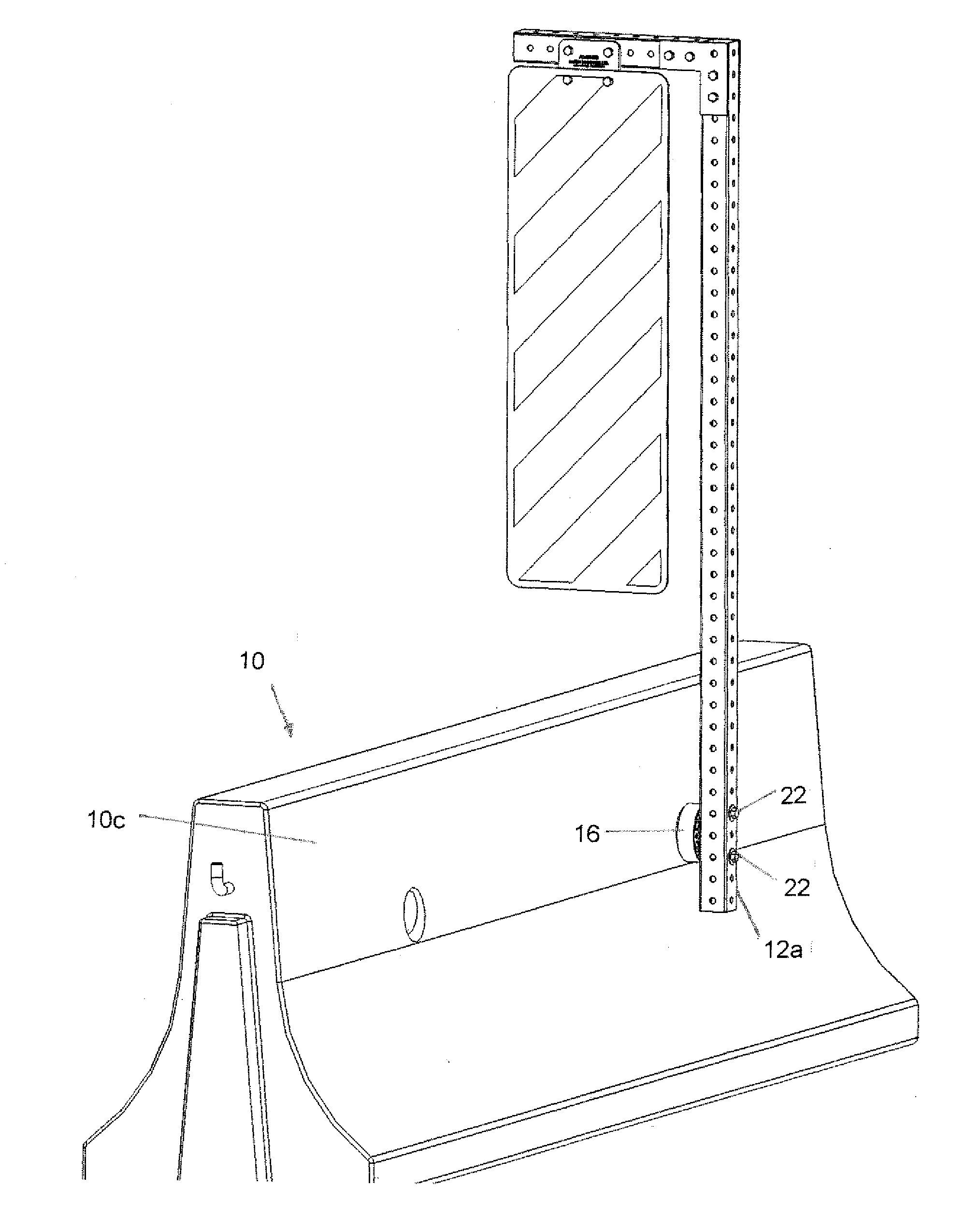
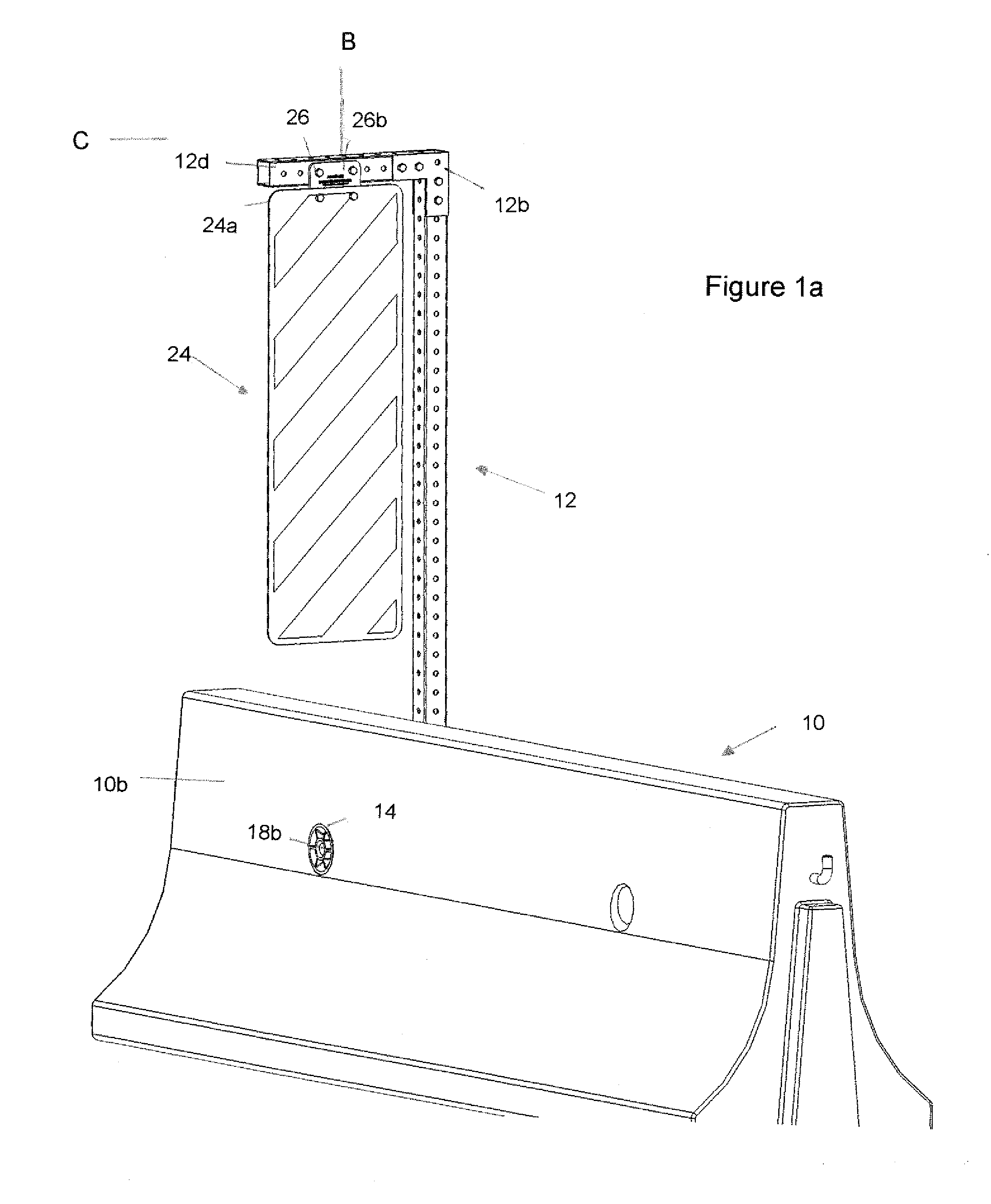
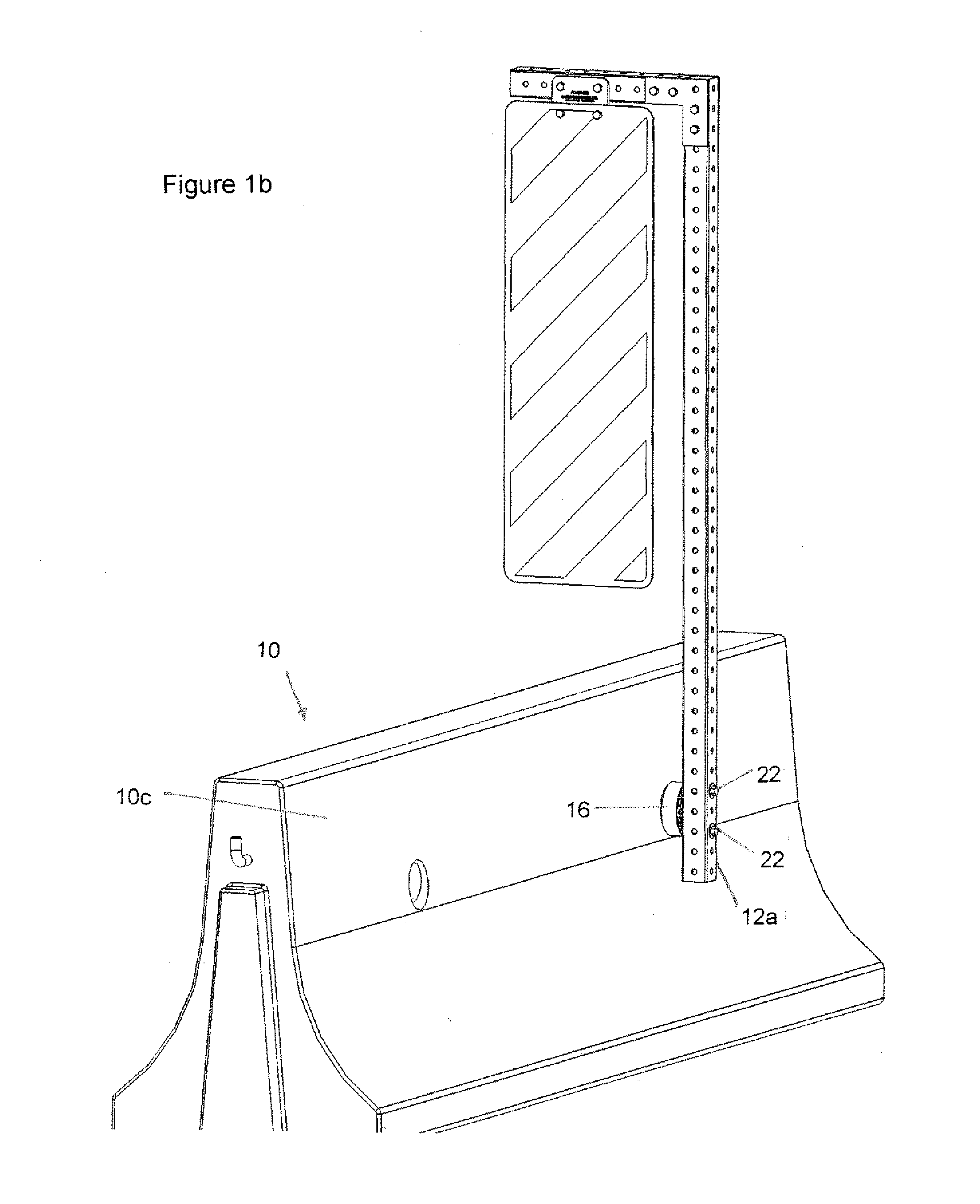
[0036]One aspect of the present invention is the provision of a barrier connector for the flush mounting of the base of a sign post to a concrete barrier using only one of the two bores which typically extend laterally completely through the concrete barrier. Typically in the prior art of which applicant is aware attempts to mount sign posts to concrete barriers have required the bracing of the post using at least two of the barrier bores so as to support the vertical sign post by triangulating the bracing upwardly between the two bores. Typically also, in prior art attempts at attaching a sign post to concrete barriers, the attachment mechanism protrudes from the road side of the barrier and, in applicant's experience, the protrusion on the roadside of the concrete barrier may be struck by a snowplough blade thereby damaging the connector and potentially knocking down the signpost.

[0037]Thus one of the objects of the present invention is to provide a simple attachment mechanism for...


PUM


Abstract

A signpost system includes a signpost system includes a signpost having a lower-most base end and an opposite upper end opposite the base end, a bore clamp including at least a traffic-side clamp member and a shoulder-side clamp member wherein the traffic-side clamp member is adapted to substantially mount flush into the traffic-side of the bore in the barrier and wherein the shoulder-side clamp member is adapted to mount onto the shoulder-side of the bore, and an elongate selectively adjustable tensioner extending from and between the clamp members for mounting the clamp members in the traffic-side and in the shoulder-side of the bore respectively, and wherein the shoulder-side clamp member is adapted for mounting to the base end of the signpost.

Description

CROSS REFERENCE TO RELATED APPLICATION[0001]This application claims priority from Canadian Patent Application No. 2,761,835 filed Dec. 12, 2011 entitled SIGN POST SYSTEM.FIELD OF THE INVENTION[0002]This invention relates to the field of traffic, roadway and highway signs and in particular to a sign post system which includes mounting signs to their corresponding sign posts and the mounting of the sign posts to concrete and other roadside barriers.BACKGROUND OF THE INVENTION[0003]One object of the present invention is to reduce the damage done to signs and their corresponding sign posts when the signs are mounted for viewing alongside roadways and highways and are suspended from a sign post which is mounted to a concrete or other roadway barrier. Typically, damage may occur when the sign or signpost is struck by snow thrown by a snowplough or is struck by the snowplough blade itself. This problem is recognized in the prior art and applicant is aware of various patent references which...

Claims


Application Information

Patent Timeline
Patent Type & Authority Patents(United States)
IPC IPC(8): G06F15/00E01F9/60
CPCF16B9/026E01F9/03G09F7/18G09F7/20E01F9/669F16B9/056
Inventor MANDL, JEFFREY ANTONMERSLACK, CLINTON BRADELY
Owner ADAPT EZE SAFETY PROD
Why Eureka
Try Eureka