
Sign post comprising composite material

a composite material and sign post technology, applied in the direction of rigid pipes, drinking vessels, display means, etc., can solve the problems of vehicle already out of control, steel posts generally not giving way upon impact, fatalities and serious injuries of vehicle occupants, etc., and achieve the effect of low cost and high strength

Active Publication Date: 2010-04-29
FRANGIBLE SAFETY POSTS
View PDF9 Cites 10 Cited by
  • Summary
  • Abstract
  • Description
  • Claims
  • Application Information

AI Technical Summary

Benefits of technology

[0006]Accordingly, it would be desirable to find an alternative composite sign post that combines high strength and good passive safety, preferably at or in the standard steel post size ranges, which for example for circular cross section posts in the UK are 88.9 mm, 114.3 mm and 139.7 mm. In particular it would be desirable to obtain a NE or LE classified composite sign post meeting strength requirements similar to or exceeding those of a steel post of the same dimensions or of a steel post with a one (standard) size down. Hence existing installation equipment should be useable with the composite sign post. It would furthermore be a desired feature that the composite post can be manufactured in an easy and convenient way at minimal cost.

Problems solved by technology

One problem with steel sign posts is that during a vehicle collision, the steel post will generally not give way upon impact.
In many cases, the vehicle is already out of control when it hits the post, so can hit it at any angle.
This type of impact can result in fatalities and serious injuries to the vehicle occupants, particularly if the impact is side-on.
However, the problem with a composite sign post based on glass fibers as disclosed in this US patent is that the stiffness performance of such a post will be at the lower end of what is required.
Alternatively, it could be contemplated to increase the diameter of the post but this would likely mean that the size would fall outside the standardized ranges of steel posts with the consequence that installation equipment adapted for use with steel posts cannot be used.
Additionally, the size of such a post might contribute to road hazards by unduly obstructing the view of road users, and become aesthetically displeasing.
This would likely lead to its rejection by highways authorities.

Method used


Image

  • Sign post comprising composite material
  • Sign post comprising composite material
  • Sign post comprising composite material

Examples


examples

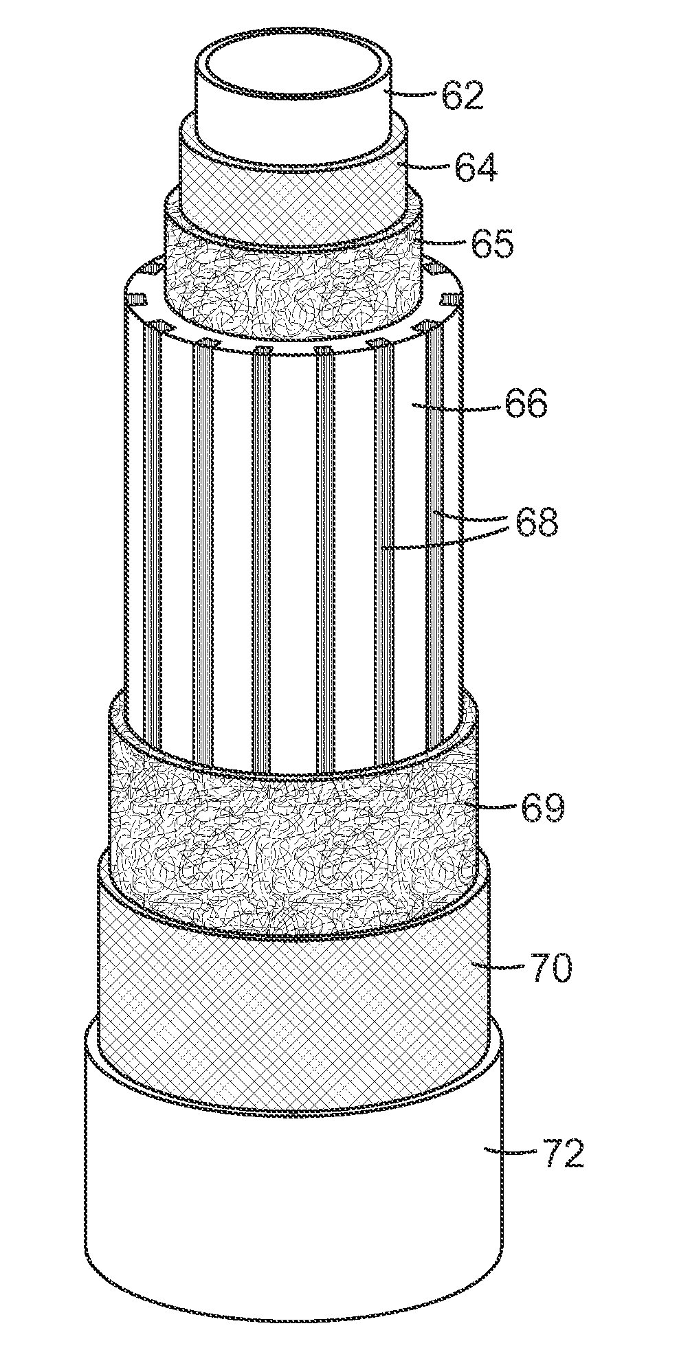
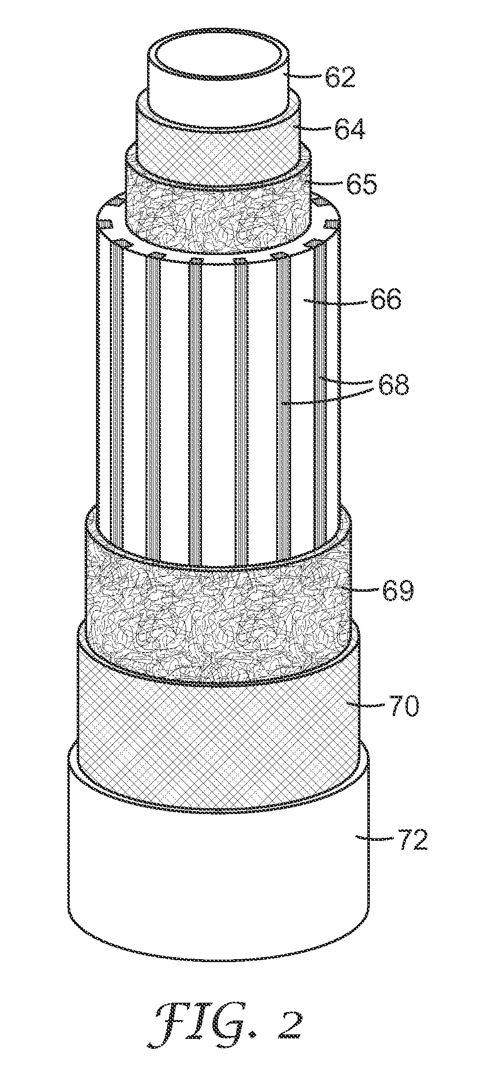
[0079]The examples were prepared by pultrusion using the apparatus specified above and the process described earlier. In the construction (FIG. 2), both veils (62,72) were omitted. Otherwise the examples were prepared as in FIG. 2. The location of the carbon tows (68) is on the outermost circumference of the longitudinal fiber composite i.e. the third concentric cylindrical array, distributed regularly in bundles. To maintain the volume of the cylindrical layer, where more carbon tows were prescribed, a corresponding number of glass rovings were omitted. An example of this is shown in FIG. 3. Thus where the table of examples refers to “24, 5×2 and 3”, this represents 5 bundles with 2 tows followed by a bundle with 3 tows. This is repeated four times to give 24 bundles regularly distributed about the circumference. FIG. 3 also shows the positions of the inner mat (64,65), the outer mat (70,69) and the longitudinal glass rovings (66).

[0080]Comparative example C1 was made as above with...


PUM

PropertyMeasurementUnit
Percent by massaaaaaaaaaa
Angleaaaaaaaaaa

Abstract

The present invention provides a tubular support (12) comprising a composite layer of resin and longitudinal arranged first fibers (66), said tubular support (12) further comprising longitudinal arranged second fibers (68) that are concentrated in discrete domains along the circumference of the tubular support, said second fibers having a Tensile modulus that is higher than the Tensile modulus of said first fibers.

Description

FIELD OF THE INVENTION[0001]The present invention relates to a tubular support, which is based on a composite material. In particular, the invention relates to tubular support posts that can be placed on the side of a street or road for example to hold signs, including traffic signs, lighting, as well as commercial signs.BACKGROUND OF THE INVENTION[0002]The vast majority of tubular support posts such as sign posts used along streets, roads and motorways are steel tubes. The steel posts are used in various sizes depending on the sign load and application conditions. Typically steel posts are available in standardized sizes and shapes and hence the installation aids to be used with these standard sizes are standardized as well. Steel posts withstand weathering for up to 15 years before they require replacement.[0003]One problem with steel sign posts is that during a vehicle collision, the steel post will generally not give way upon impact. Because the post remains rigid close to groun...

Claims


Application Information

Patent Timeline
IPC IPC(8): E01F9/011B32B1/08B29C70/52
CPCB29C45/14631Y10T428/1317B29C70/207B29C70/521B29D23/001B29K2707/04B29K2709/08B29L2009/003B29L2023/22B32B1/08B32B5/08B32B17/04E01F9/011E04H12/02Y10T428/1369Y10T428/1362Y10T428/1321Y10T428/1352Y10T428/1314B29C70/12E01F9/623E01F9/60E01F9/631B29D23/00B32B17/02
Inventor BOYCE, GERARD S.
Owner FRANGIBLE SAFETY POSTS
Learn More