Fuel cell system

a fuel cell and system technology, applied in the field of fuel cell systems, can solve the problems of consuming fuel in the fuel cell stack, triggering automatic stopping of the fuel cell system, and affecting the optimal supply of gas to the cell stack, so as to achieve stable operation and improve the use of the generated electric power of the fuel cell

Active Publication Date: 2014-02-04
TOYOTA JIDOSHA KK
View PDF19 Cites 1 Cited by
  • Summary
  • Abstract
  • Description
  • Claims
  • Application Information

AI Technical Summary

Benefits of technology

[0008]The present invention advantageously enables more effective use of generated electric power of a fuel cell, and enables stable operation by enabling release of a stuck valve in a fuel cell system.
[0010]Further, preferably, the fuel cell system includes an oxidized gas supply flow path supplying the oxidized gas to the fuel cell, an oxidized gas related exhaust flow path exhausting the oxidized gas related gas from the fuel cell, a fuel cell bypass flow path connecting the oxidized gas supply flow path and the oxidized gas related exhaust flow path and bypassing the fuel cell, and a fuel cell bypass valve provided in the fuel cell bypass flow path, and the pressure changing unit open the fuel cell bypass valve by a predetermined amount at a starting time, and increase a pressure value of a fluid to be supplied to the pressure chamber to be larger than the first pressure value by restricting an opening of the fuel cell bypass valve under abnormal conditions in which the valve does not function even when the pressure inside the pressure chamber is at the first pressure value.
[0016]A fuel cell system according to the present invention comprises a valve which functions in accordance with pressure change of the fluid supplied from the fluid supply section, pressure applying unit which drive the valve by causing the pressure at the first pressure value to act on the pressure chamber communicating with the fluid supply section, and pressure changing unit which change the pressure at the first pressure value inside the pressure chamber under abnormal conditions in which the valve does not function, even when the pressure inside the pressure chamber is at the first pressure value. Therefore, even when the valve is stuck, the valve can be released by changing the pressure at the first pressure value inside the pressure chamber communicating with the fluid supply section to rise or the like using the fuel cell bypass valve or the fluid supply section controlling unit, and stable operation can be performed. In addition, as there is no need to consume the fuel inside the fuel cell in order to drive the valve, and generated electric power of the fuel cell can be used more effectively.

Problems solved by technology

When the valves do not function and do not normally open, the optimal supply of gas to the cell stack and of discharge gas from the cell stack are impaired, and, in an extreme case, there is a possibility that automatic stopping of the operation of the fuel cell system could be triggered.
Further, when it is determined that an opening failure occurs to the valve, the fuel in the fuel cell stack is consumed which increases the differential pressure between the flow path in front of and behind the valve.

Method used


Image

  • Fuel cell system
  • Fuel cell system
  • Fuel cell system

Examples


first embodiment

of the Invention

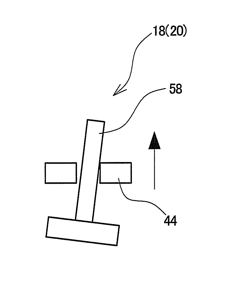
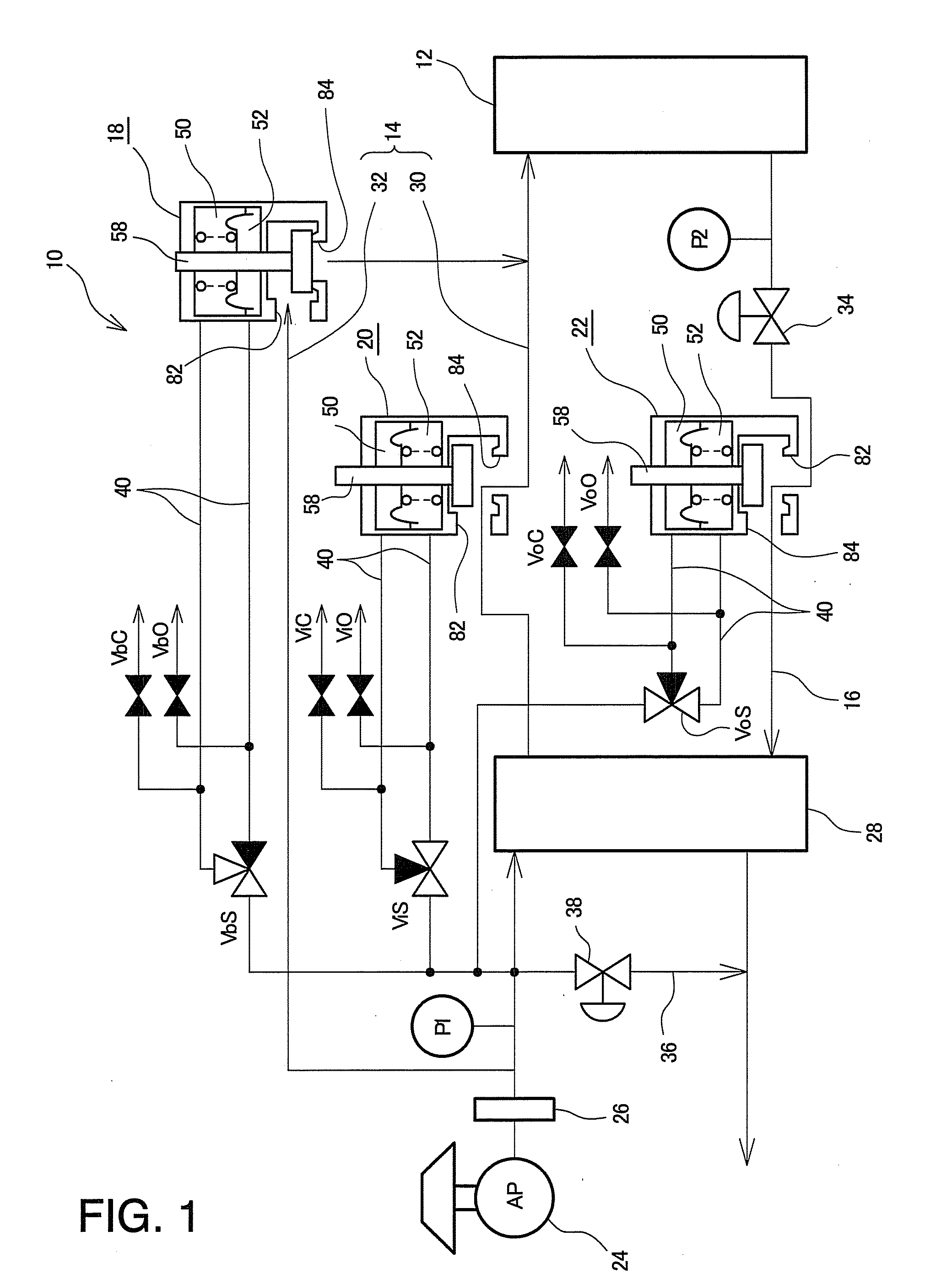
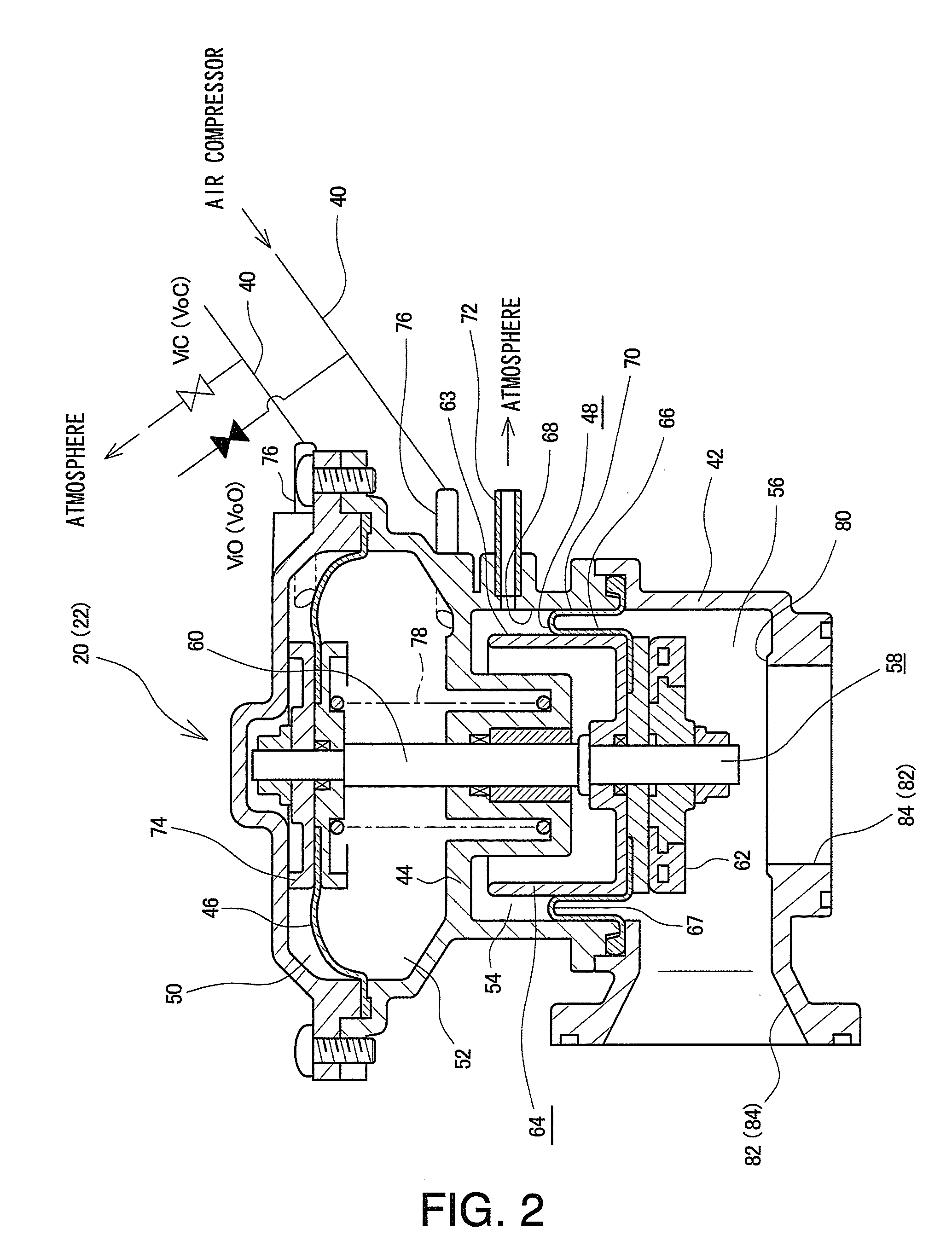
[0031]Hereinafter, embodiments of the present invention will be described with reference to the drawings. FIGS. 1 to 6 show a first embodiment of the present invention. FIG. 1 is a schematic block diagram of a fuel cell system according to the first embodiment. The fuel cell system 10 includes a fuel cell stack 12, an oxidized gas supply flow path 14, an oxidized gas related exhaust flow path 16, a humidifier bypass valve 18, an inlet shutoff valve 20 and an outlet shutoff valve 22.

[0032]The fuel cell stack 12 generates electric power through an electrochemical reaction of oxygen and hydrogen. That is, by supplying hydrogen gas as fuel gas, and air as oxidized gas to the fuel cell stack 12, the oxygen and hydrogen electrochemically react and electric energy is obtained in a plurality of fuel cells, not illustrated, in the fuel cell stack 12. Each fuel cell includes a membrane-electrode assembly formed by, for example, an electrolyte membrane, an anode electrode, a ca...

second embodiment

of the Invention

[0090]FIG. 7 is a flowchart showing a start control method according to a second embodiment of the present invention. In the following description, the basic configuration of the fuel cell system is the same as that of the first embodiment shown in of FIG. 1, and therefore the same reference numerals and characters as used above will be assigned to portions equivalent to those of the configuration of FIG. 1. First, a start control method when first only the humidifier bypass valve 18 among the humidifier bypass valve 18 and the inlet shutoff valve 20 is opened at the time of start-up of power generation, and thereafter, only the inlet shutoff valve 20 is opened, will be described.

[0091]In the case of the present embodiment, there is provided the pressure applying unit which drive one of the humidifier bypass valve 18 and the inlet shutoff valve 20 by causing the pressure at the first pressure value corresponding to the first discharge pressure of the air compressor 2...

third embodiment

of the Invention

[0100]Although not illustrated, the first embodiment shown in the above-described FIGS. 1 to 6 and the second embodiment shown in the above-described FIG. 7 can be combined as a third embodiment of the present invention. Specifically, the present embodiment will be described hereinafter with use of the reference numerals and characters of FIG. 1 showing the above-described first embodiment; the present embodiment includes the pressure applying unit which cause the pressure at the first pressure value corresponding to the first discharge pressure of the air compressor 24 to act on the valve opening pressure chamber 52 which communicates with the air compressor 24, in one of the humidifier bypass valve 18 and the inlet shutoff valve 20, and thereby drive the above-described one valve, as in each of the embodiments described above. In the present embodiment are employed, corresponding to the pressure changing unit provided to the control unit in the first embodiment as ...


PUM

PropertyMeasurementUnit
electric poweraaaaaaaaaa
pressureaaaaaaaaaa
discharge flow rateaaaaaaaaaa

Abstract

A fuel cell system has an inlet shutoff valve provided in a main route forming an oxidized gas supply flow path, a humidifier bypass valve provided in a humidifier bypass route which is a route bypassing the main route, a fuel cell bypass valve provided in a fuel cell bypass route bypassing a fuel cell stack, and fuel cell bypass valve controlling unit. Under abnormal conditions in which one of the inlet shutoff valve and the humidifier bypass valve does not function even if the pressure in a valve opening pressure chamber of the one of the valves is at a first pressure value, the fuel cell bypass valve controlling unit restrict the opening of the fuel cell bypass valve to increase the pressure in the valve opening pressure chamber.

Description

[0001]This is a 371 national phase application of PCT / JP2008 / 054686 filed 7 Mar. 2008, claiming priority to Japanese Patent Application No. JP 2007-059709 filed 9 Mar. 2007, the contents of which are incorporated herein by reference.TECHNICAL FIELD[0002]The present invention generally relates to a fuel cell system including a fuel cell which generates electric power through an electrochemical reaction of a fuel gas and an oxidized gas.TECHNICAL BACKGROUND[0003]A fuel cell system includes fuel cells which generate electric power through an electrochemical reaction of a reactant gas (fuel gas and an oxidized gas), a reactant gas supply flow path for supplying the reactant gas to the fuel cells, and a reactant gas related exhaust flow path for exhausting the reactant gas from the fuel cells. Additionally, the provision of fuel cell shutoff valves in the reactant gas and reactant gas related exhaust flow paths has been considered.[0004]For example, the fuel cell system described in Japa...

Claims


Application Information

Patent Timeline
Patent Type & Authority Patents(United States)
IPC IPC(8): H01M8/04
CPCH01M8/04753H01M8/04761Y02E60/50H01M8/04089Y02T90/32H01M2250/20H01M8/04223H01M8/04141H01M8/04201H01M8/04395H01M8/04225H01M8/04302H01M8/2457Y02T90/40H01M8/04
Inventor OSADA, YASUHIROBONO, TETSUYA
Owner TOYOTA JIDOSHA KK
Why Eureka
Try Eureka