Detection of fuel contamination in lubricating oil
What is AI technical title?
AI technical title is built by Patsnap AI team. It summarizes the technical point description of the patent document.
a technology of lubricating oil and detection field, applied in the direction of resistance/reaction/impedence, instruments, measurement devices, etc., can solve the problems of engine failure, reducing the lubricating ability of oil, and reducing the viscosity of oil
Inactive Publication Date: 2014-02-04
VOELKER SENSORS
View PDF42 Cites 39 Cited by
Summary
Abstract
Description
Claims
Application Information
AI Technical Summary
This helps you quickly interpret patents by identifying the three key elements:
Problems solved by technology
Method used
Benefits of technology
Problems solved by technology
Fuel contamination in crankcase oil decreases the lubricating ability of oil and will lead to engine failure.
If a fuel injector becomes stuck in the open position, the introduction of large amounts of fuel in crankcase oil will decrease the viscosity of the oil.
If the fuel contamination goes undetected, the decrease in viscosity will cause a loss of hydrodynamic lubrication resulting in metal to metal contact and ultimately causing spun and / or seized bearings.
The difficulties in applying absorbance spectroscopy to an in-situ device are significant and make this particular detection technique impractical.
However, oil wear, water contamination, and soot contamination all cause an increase the viscosity of the oil making the detection of fuel contamination in oil by measuring its viscosity difficult.
A sniffer requires constant calibration with a known fuel / oil mixture which is impractical in an in-situ device.
Still further, fuel does not significantly change other measurable qualities of the oil (conductivity, dielectric constant, resistance, capacitance, polarity, TAN, TBN etc) so a direct in-situ electrical or chemical measurement of the oil to detect the presence of fuel is difficult.
Method used
Image
Click on the blue label to locate the original text in one second.
Reading with bidirectional positioning of images and text.
Examples
Embodiment Construction
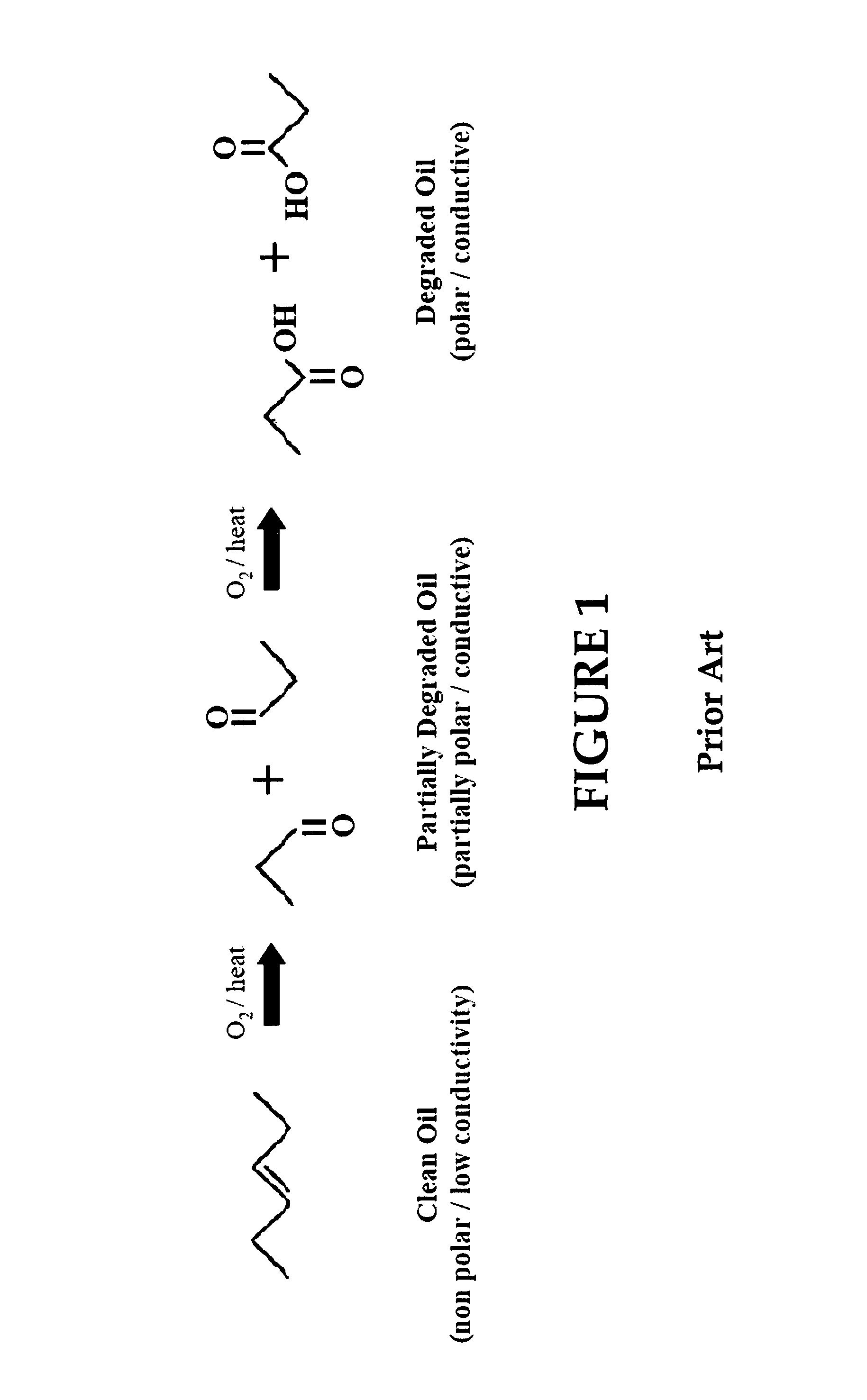
[0020]FIG. 1 illustrates oil that, initially, is clean and non-polar. In the presence of O2 and heat, the oil begins to degrade. This application of O2 and heat would occur through, for example, the normal and ongoing use of the oil in an automobile. This partially degraded oil, as also shown in FIG. 1, begins to take on polar characteristics. Through the continued application of O2 and heat, the oil becomes even more degraded and takes on even greater polar characteristics as further shown in FIG. 1. Increased polarity causes the oil to change is dielectric constant, which in turn leads to increased capacitance.
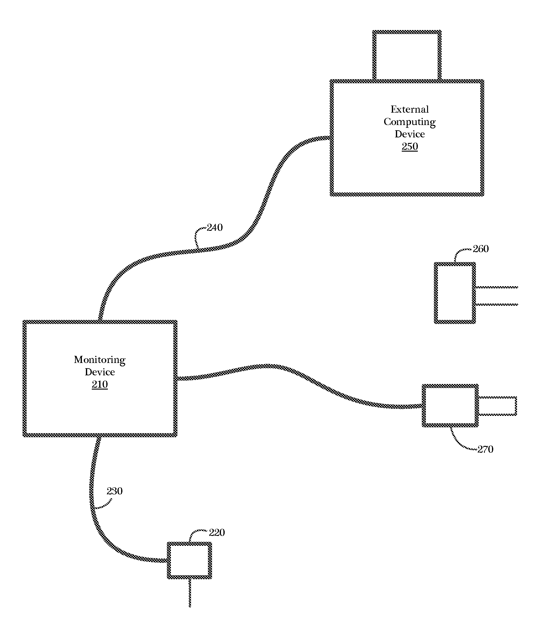
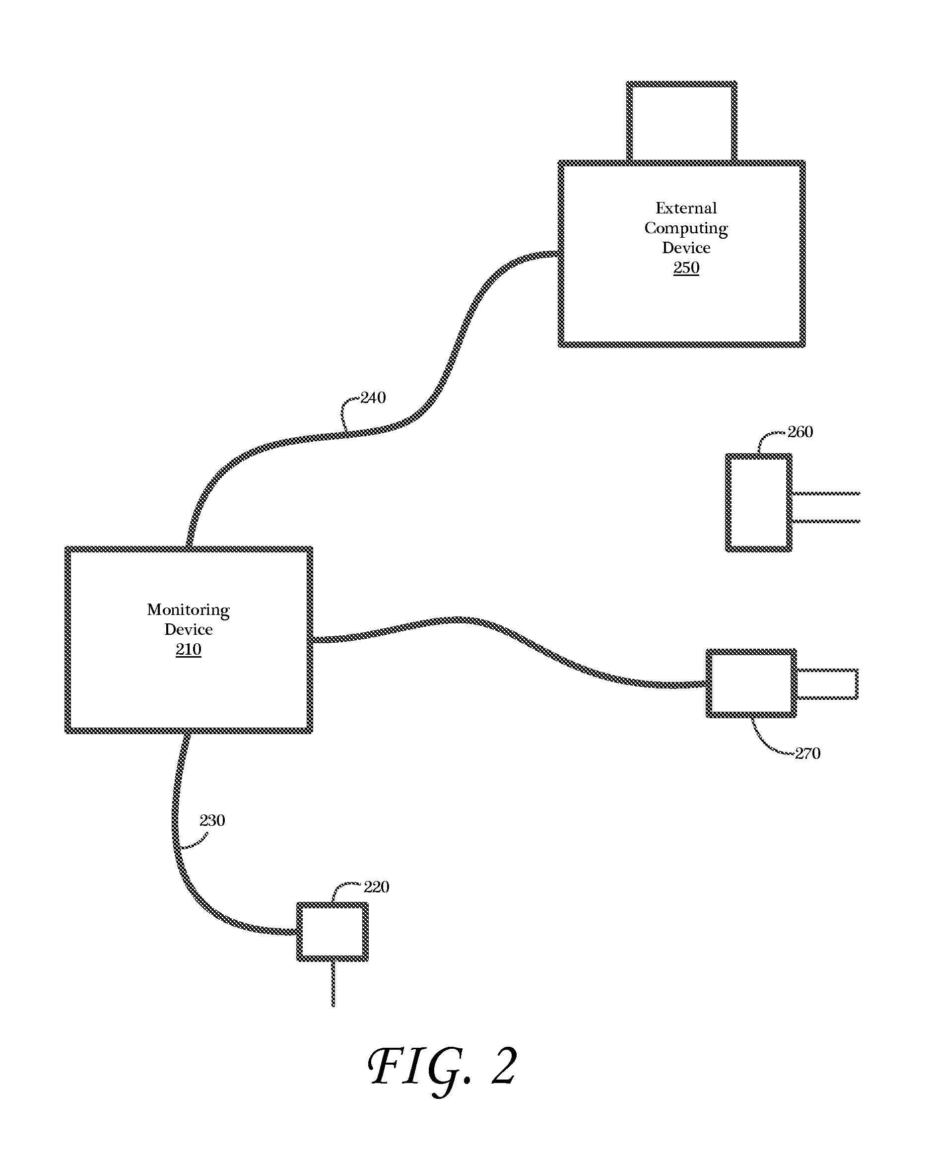
[0021]FIG. 2 illustrates an exemplary real-time oil monitoring system 200 as may be implemented in accordance with an embodiment of the present invention. An embodiment of the oil monitoring system 200 may comprise a monitoring device 210 for receiving and analyzing data generated by a sensing element 220, which is in contact with the oil or other fluid under observation.
[00...
PUM
Abstract
A method for measuring fuel contamination in oil that uses a material in contact with oil whereby fuel intrusion into the oil will change the electrical, mechanical, and / or chemical properties of the material as compared to the same electrical, mechanical, and / or chemical properties of the material when in contact only with mineral or synthetic oil only.
Description
CROSS-REFERENCE TO RELATED APPLICATIONS[0001]The present application is a continuation in part and claims the priority benefit of U.S. patent application Ser. No. 12 / 426,956 filed Apr. 20, 2009, now U.S. Pat. No. 7,928,741, which is a continuation and claims the priority benefit of U.S. patent application Ser. No. 11 / 676,738, now U.S. Pat. No. 7,521,945, filed Feb. 20, 2007, which claims the priority benefit of U.S. provisional patent application No. 60 / 774,749 filed Feb. 17, 2006 and U.S. provisional patent application No. 60 / 782,959 filed Mar. 15, 2006. The disclosure of the aforementioned applications is incorporated herein by reference.[0002]The present application is related to U.S. Pat. No. 5,435,170, entitled “Method and Apparatus for Fluid Quality Sensing”; U.S. Pat. No. 5,777,210, entitled “Oil Quality Sensor Measuring Bead Volume”; and U.S. Pat. No. 5,789,665 entitled “Oil Quality Sensor for Use in a Motor Oil.” The disclosure of these commonly owned patents is incorporate...
Claims
Application Information
Patent Timeline
Application Date:The date an application was filed.
Publication Date:The date a patent or application was officially published.
First Publication Date:The earliest publication date of a patent with the same application number.
Issue Date:Publication date of the patent grant document.
PCT Entry Date:The Entry date of PCT National Phase.
Estimated Expiry Date:The statutory expiry date of a patent right according to the Patent Law, and it is the longest term of protection that the patent right can achieve without the termination of the patent right due to other reasons(Term extension factor has been taken into account ).
Invalid Date:Actual expiry date is based on effective date or publication date of legal transaction data of invalid patent.

