Oscillator circuit

a technology of oscillator and circuit, which is applied in the direction of pulse generator, pulse generation by vacuum tubes, pulse technique, etc., can solve the problems of clock signal frequency variation, reduce or at least alleviate the effect of clock output signal fout frequency variation, constant charging ra

Active Publication Date: 2014-02-04
NXP USA INC
View PDF7 Cites 2 Cited by
  • Summary
  • Abstract
  • Description
  • Claims
  • Application Information

AI Technical Summary

Benefits of technology

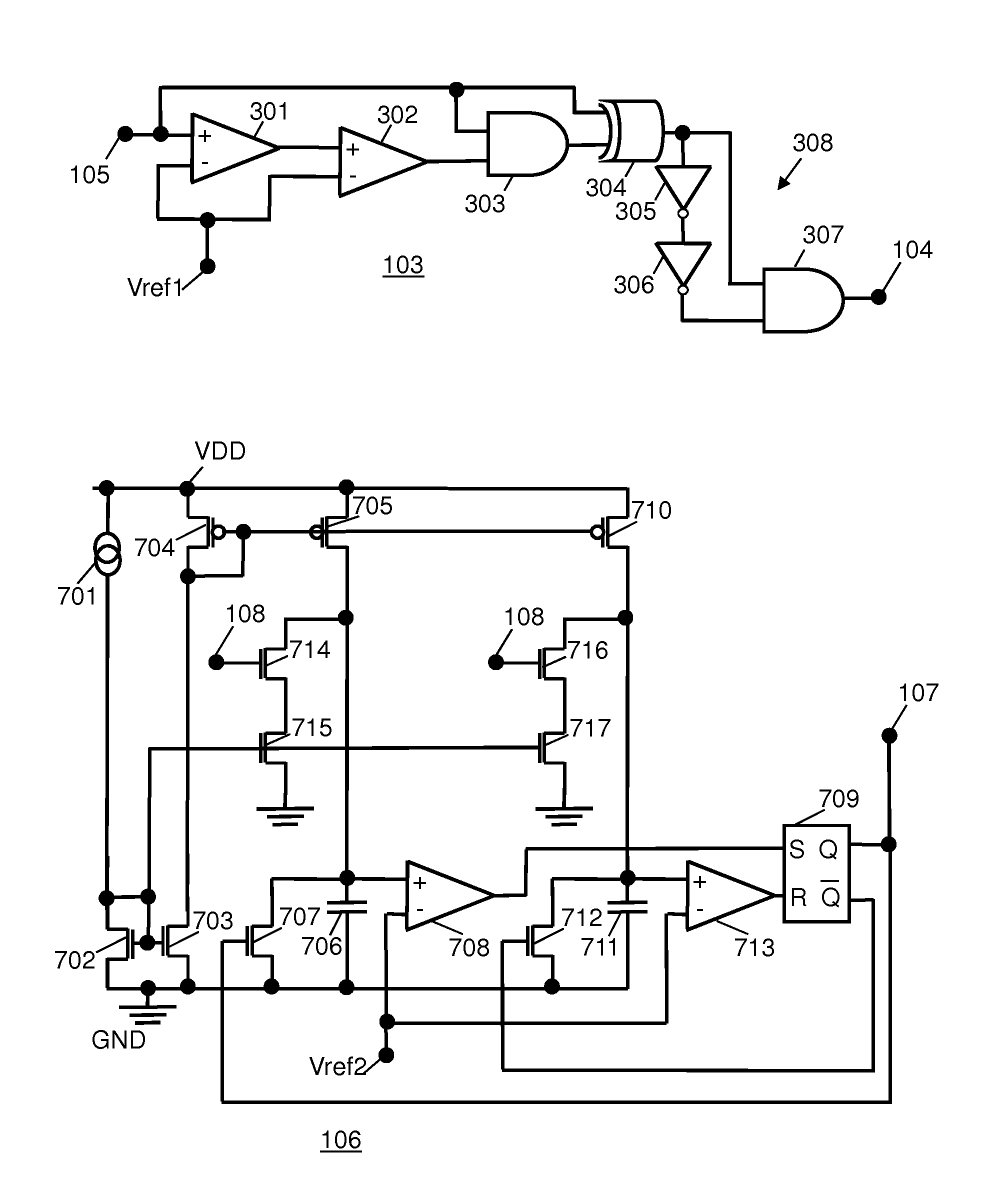
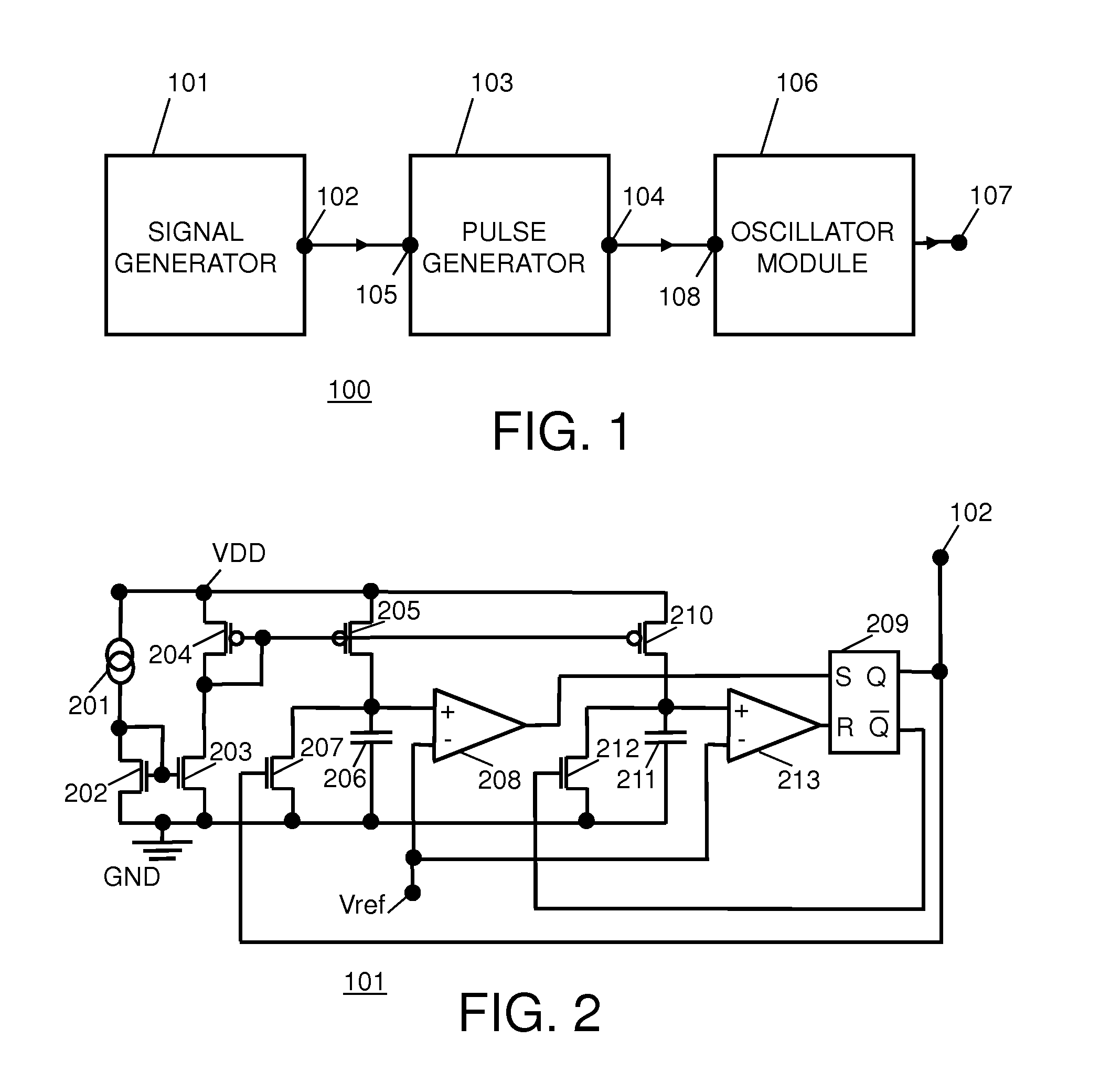
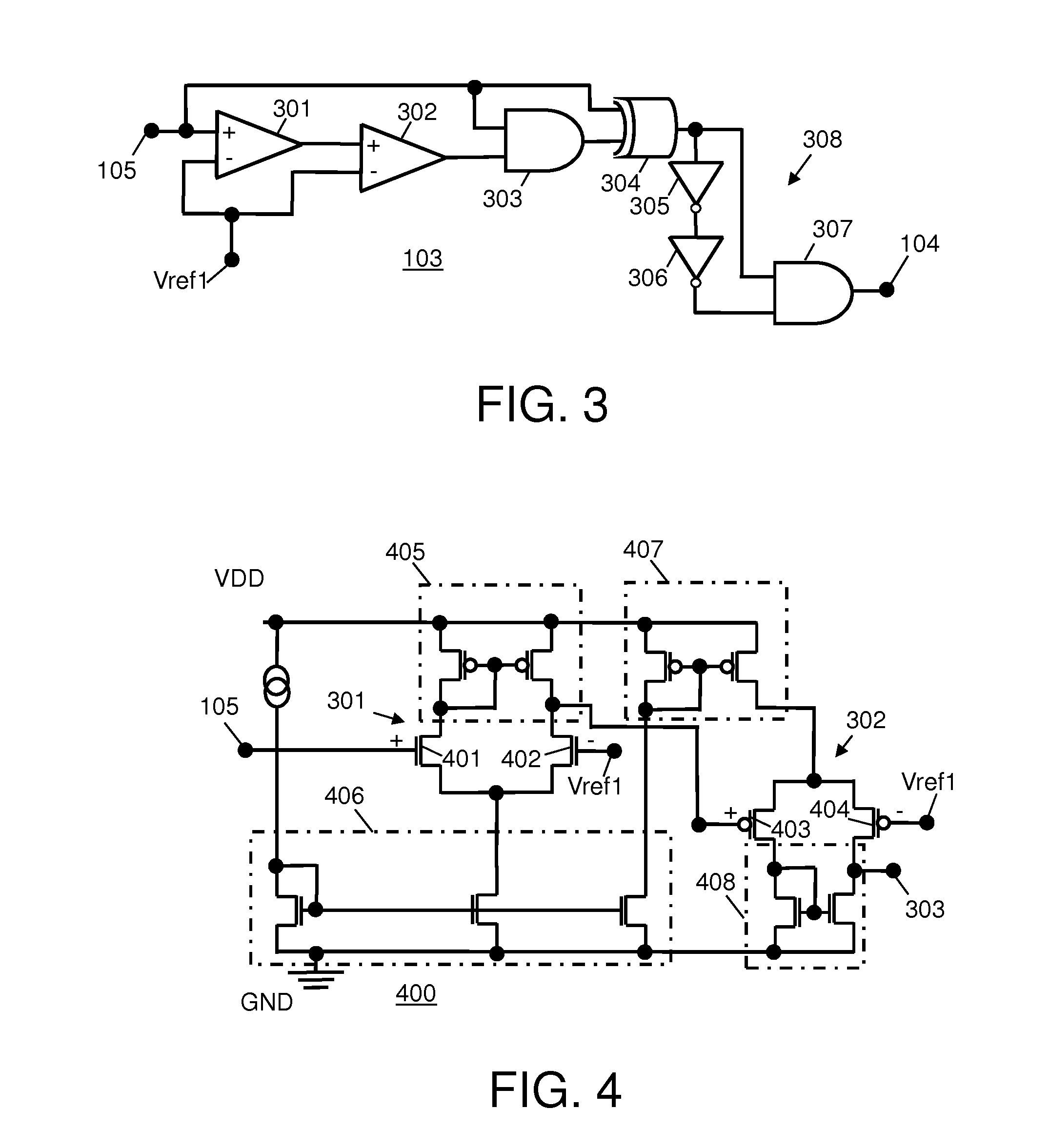
[0038]Advantageously, the present invention reduces or at least alleviates the effects of clock output signal Fout frequency variations caused by ambient temperature variations. This is because the compensation binary pulses Cp have a substantially constant pulse duration D regardless of variations in the duty cycle of the compensation binary pulses Cp. Therefore, drift variations in electrical characteristics of the set and reset capacitors 706, 711 are offset by variations in a duty cycle of the compensation binary pulses Cp that provide for maintaining substantially constant charging rates of the capacitors 706, 711.

Problems solved by technology

However, ambient temperature variations and process drift can cause variations in electrical characteristics of these capacitors and transistors thereby causing the frequency of the clock signal to vary.

Method used


Image

  • Oscillator circuit
  • Oscillator circuit
  • Oscillator circuit

Examples


Embodiment Construction

[0012]The detailed description set forth below in connection with the appended drawings is intended as a description of presently preferred embodiments of the invention, and is not intended to represent the only forms in which the present invention may be practiced. It is to be understood that the same or equivalent functions may be accomplished by different embodiments that are intended to be encompassed within the spirit and scope of the invention. In the drawings, like numerals are used to indicate like elements throughout. Furthermore, terms “comprises,”“comprising,” or any other variation thereof, are intended to cover a non-exclusive inclusion, such that module, circuit, device components, method steps and structures that comprises a list of elements does not include only those elements but may include other elements not expressly listed or inherent to such module, circuit, steps or device components. An element or step proceeded by “comprises” does not, without more constrain...


PUM


Abstract

An oscillator circuit includes a signal generator having a compensation frequency output node that provides a compensation frequency signal at the compensation frequency output node. A pulse generator having a pulsed signal output node and a pulse generator input node is coupled to the compensation frequency output node and converts the compensation frequency signal into a series of compensation binary pulses having a constant pulse duration regardless of variations in the duty cycle of the compensation binary pulses. An oscillator module having at least two capacitors, an oscillator output node and a pulsed signal input node is coupled to the pulsed signal output node, and provides an output signal that is at a frequency dependent on charging rates of the capacitors. Drift variations in the capacitors are offset by variations in a duty cycle of the compensation binary pulses supplied in order to maintain constant charging rates of the capacitors.

Description

BACKGROUND OF THE INVENTION[0001]The present invention relates to oscillators, and more particularly, to oscillators with sampling current compensation for offsetting drift variations.[0002]Oscillator circuits are found in many electronic circuit applications and are often used for generating clock signals that control the timing of circuits or control the logic state of a device. For example, oscillator circuits can be used in conjunction with many circuits such as DC / DC converters, audio receivers, counters, shifters, microprocessors and FM (frequency modulation) circuitry. Typically, the frequency of the clock signal provided by an oscillator circuit is determined primarily by charging and discharging of one or more capacitors. Such charging and discharging is often controlled by constant current sources or current mirrors supplying charge currents to the capacitors and the discharging is effected by controlling transistors coupled across the capacitors. However, ambient temperat...

Claims


Application Information

Patent Timeline
Patent Type & Authority Patents(United States)
IPC IPC(8): H03K3/0231
CPCH03K3/02315
Inventor WANG, MENG
Owner NXP USA INC
Why Eureka
Try Eureka