Radio frequency positioning system for vehicles

a vehicle and positioning system technology, applied in the direction of direction finders using radio waves, using reradiation, radio wave reradiation/reflection, etc., can solve the problems of limiting the possibility of storing goods, positioning shelves, etc., in the warehouse itself, and even significant localisation errors, etc., to achieve easy installation and high vehicle localisation accuracy

Inactive Publication Date: 2014-02-04
ELETTRIC 80 SPA
View PDF18 Cites 17 Cited by
  • Summary
  • Abstract
  • Description
  • Claims
  • Application Information

AI Technical Summary

Problems solved by technology

For this reason, it is necessary to reserve a portion of the inside surfaces of the warehouse for positioning the reflectors to the disadvantage of the actually usable space.
Laser positioning systems operate with a rotating head that projects the laser beam on horizontal scanning plane, thus they exhibit the problem of ensuring not only a direct optical line between the vehicle laser beam and the reflectors positioned within the warehouse, but an entire horizontal scanning plane completely free from obstacles in the entire warehouse.
Therefore, there are consequent limits to the possibilities of storing goods, positioning shelves, etcetera, in the warehouse itself as they may interfere with the optical line between the vehicle laser head and the reflectors, and moreover it is often necessary to position the laser head on top of a telescopic shaft enabling it to operate on an obstacle-free horizontal plane.
Another problem of laser positioning systems that implies even significant localisation errors is due to the laser beams that may accidentally be reflected by the metal walls within the warehouse, for example by metal shelves, or by any other obstacle having reflecting features.
Accidentally reflected laser beams reach the vehicle receiving head, which does not make a distinction between the beams properly reflected by the reflectors and the accidentally reflected beams, thus generating errors about the positioning of the moving vehicle.
A further defect of the above laser positioning system is given by the fact that it is not possible to have information about the reflector that reflects the laser beam, that is, it is not possible to identify which reflector has reflected the laser beam emitted by the head.
localisation errors due to the vehicle inclination in certain situations and to the consequent inclination of the telescopic shaft that causes the laser beam to deviate from the horizontal plane where the reflectors are;
limited possibility of extending the telescopic shaft whereon the laser head is mounted.
Recently, three-dimensional laser systems have been introduced which partly solve the above problems, to the disadvantage of a reduced scanning speed.
However, experiments have shown that the actual accuracies that may be achieved in localising a vehicle do not exceed 30 cm, in the current more advanced systems, due to the problem caused by multiple paths, or “multipaths”, of the radio or electromagnetic waves within the area.
Of course, 30 cm accuracy localisation values are unacceptable for applications in areas like warehouses, stores etcetera.
This type of solution cannot be used for portable positioning systems as it would be too cumbersome and unpractical, but for some types of vehicles, for example automatic guided vehicles, this size may be reduced within admissible limits.

Method used


Image

  • Radio frequency positioning system for vehicles
  • Radio frequency positioning system for vehicles
  • Radio frequency positioning system for vehicles

Examples


Embodiment Construction

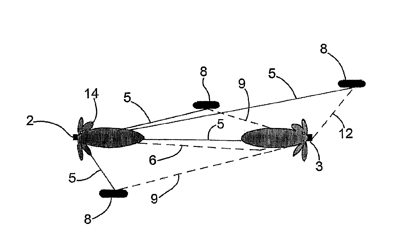
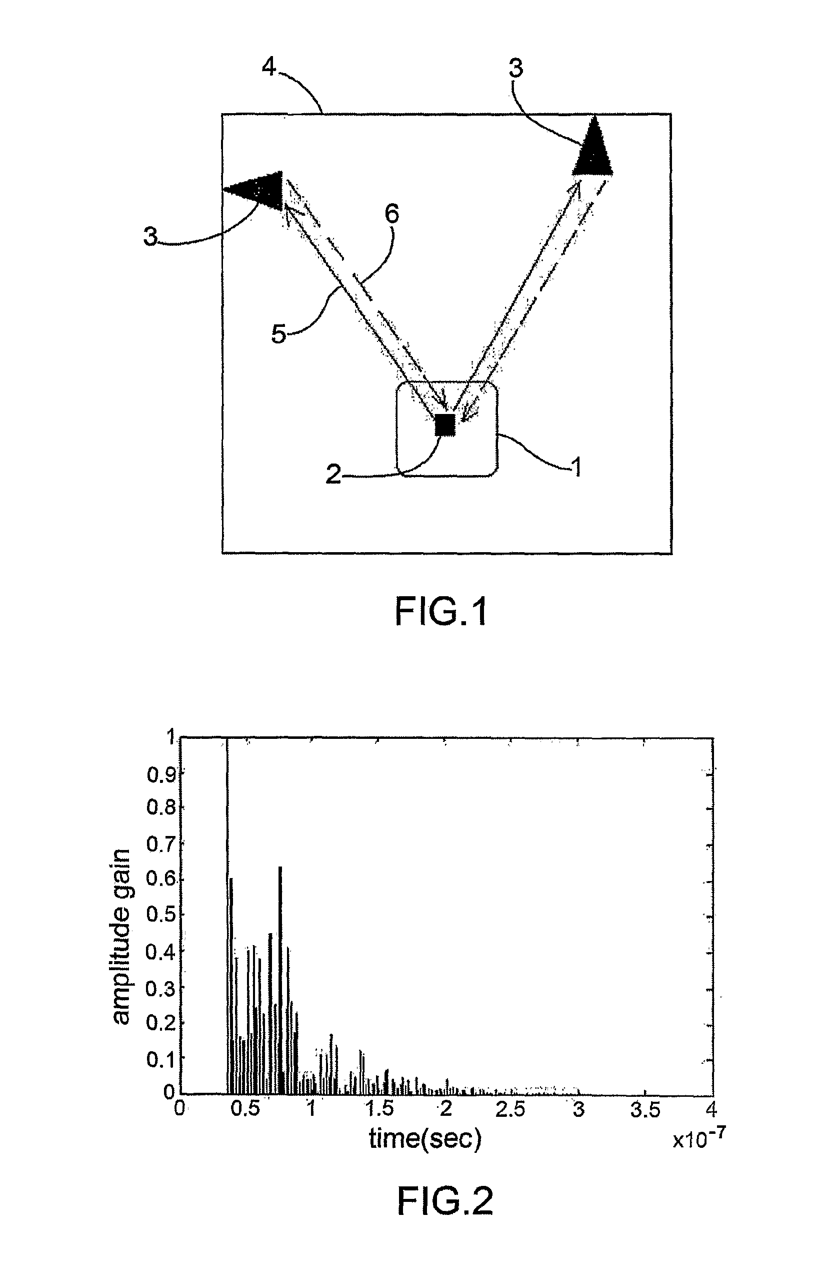
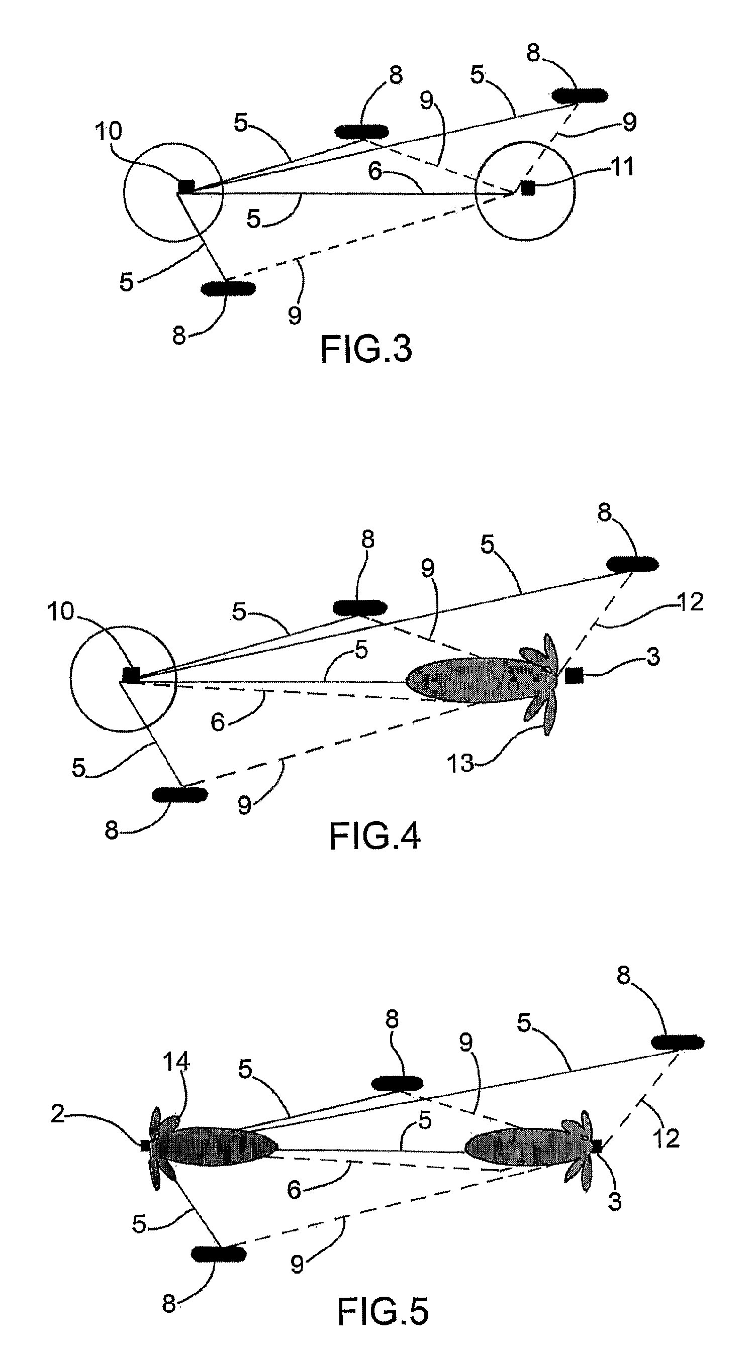
[0059]According to what shown in the annexed figures, the positioning system according to the present invention essentially comprises some reference antennas 3 located in known positions of an area 4, in particular a closed area, for example a warehouse or a store, wherein vehicles 1 to be localised move, in turn provided with a two-way radio directive or omnidirectional antenna 2. As will appear more clearly in the following description, vehicles 1 may be automatic guided vehicles, also called AGV vehicles, or manual guided vehicles, that is, guided by an operator.

[0060]In the case of AGV vehicles, the positioning system according to the present invention provides the necessary information for the vehicle movement to the automatic guide devices.

[0061]In the case of manual guided vehicles, the positioning system according to the present invention provides the operator with the information on the presence of other vehicles in the zone and optionally, for safety reasons, it may also i...


PUM


Abstract

A positioning system for radio frequency devices includes a two-way radio antenna, for vehicles, having a transmitting and a receiving element. Reference antennas have retro-directive arrays which can shape the signal beams in elevation; polarize transmission and reception signals according to a circular or a linear polarization, the polarized transmission retro-directively reflecting signals having the same polarization as the incident ones in the case of circular polarization, or retro-directively reflecting signals having orthogonal polarization in the case of linear polarization. An encoder is included for transmitting an identification code of the reference antenna. A controller processes the spatial and temporal data resulting from communication through the radio waves transmitted and received by the vehicle antennas and reflected by the reference antennas. The controller calculates the distance of the vehicle from the reference antennas that have reflected the signal transmitted by the antennas.

Description

TECHNICAL FIELD OF THE INVENTION[0001]The present invention relates to radio frequency positioning system for vehicles, for example automatic guided vehicles, with radio frequency antennas located on the vehicles themselves and reference antennas located in predetermined positions of an area in which the vehicles are moving.[0002]According to a version of the present invention, the reference antennas of the area in which the vehicles are moving comprise the so-called retro-directive arrays, abbreviated as RDA.[0003]According to another version of the present invention, the antennas on the vehicle may be of the directive type and may optionally operate in combination with the reference antennas of the area, provided with retro-directive arrays.[0004]The present invention is used for detecting the position of a vehicle, for example a manual guided vehicle, or an automatic guided vehicle, abbreviated as AGV, especially within areas of the closed type, for example warehouses, stores, et...

Claims


Application Information

Patent Timeline
Patent Type & Authority Patents(United States)
IPC IPC(8): G01S13/42
CPCG01S13/756G01S13/825G01S13/876H01Q21/065G01S7/35G01S7/024G01S13/767H01Q3/46
Inventor CAVIRANI, VITTORIOTROTTA, FRANCESCOMARCACCIOLI, LUCAVINCENTI GATTI, ROBERTOMANZINI, FRANCODI TERLIZZI, DOMENICO
Owner ELETTRIC 80 SPA
Why Eureka
Try Eureka