
End-loaded topology for D-plane polarization improvement

a d-plane polarization and end-loaded topology technology, applied in the direction of slot antennas, polarised antenna unit combinations, antennas, etc., can solve the problems that existing designs and design techniques have not been able to provide a tapered slot antenna element, and achieve the effect of increasing d-plane polarization control

Active Publication Date: 2014-02-11
RAYTHEON CO
View PDF7 Cites 0 Cited by
  • Summary
  • Abstract
  • Description
  • Claims
  • Application Information

AI Technical Summary

Benefits of technology

This design enhances D-plane polarization control, maintaining gain, bandwidth, and scan volume while reducing unwanted coupling, and is more manufacturable than previous solutions, with testing showing approximately twice the polarization control of similar tapered notch elements without increased costs or complexity.

Problems solved by technology

Existing designs and design techniques have not been able to provide a tapered slot antenna element which compensates for D-plane polarization instability without sacrificing gain, bandwidth, scan volume, or manufacturability of the array.

Method used


Image

  • End-loaded topology for D-plane polarization improvement
  • End-loaded topology for D-plane polarization improvement
  • End-loaded topology for D-plane polarization improvement

Examples


Embodiment Construction

.”

BRIEF DESCRIPTION OF THE DRAWINGS

[0026]Features, aspects, and embodiments are described in conjunction with the attached drawings, in which:

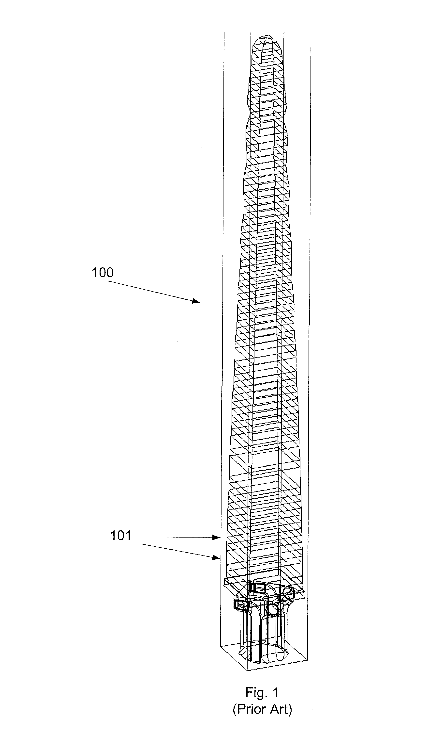
[0027]FIG. 1 is a perspective view of a tapered notch antenna element according to the prior art.

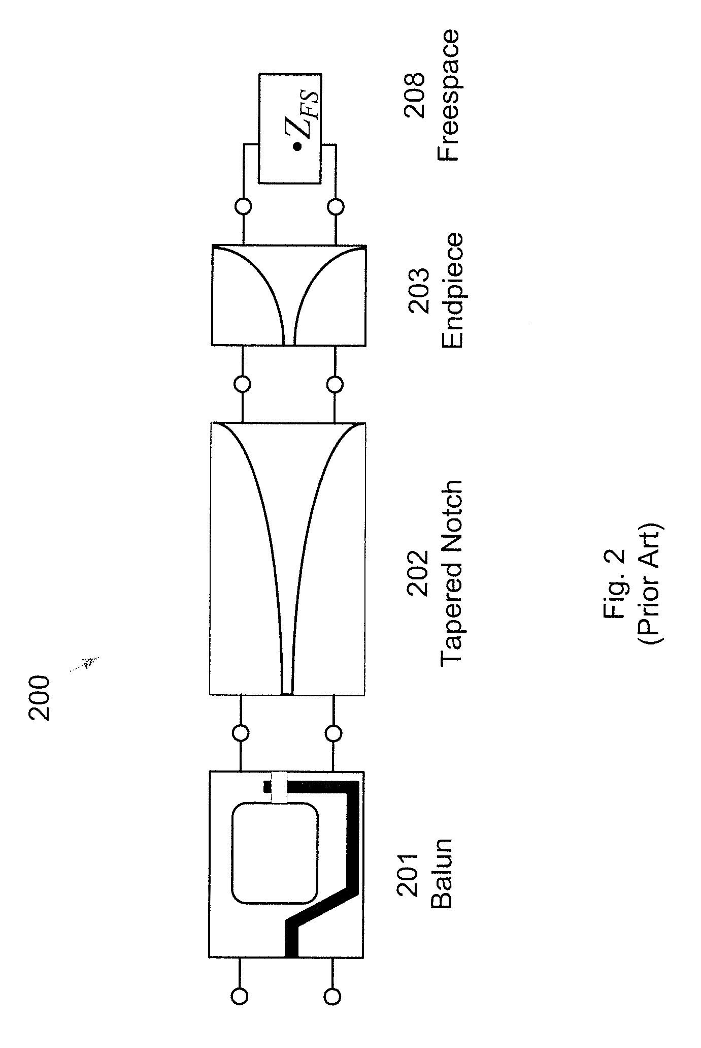
[0028]FIG. 2 is a block diagram illustrating an antenna element according to the prior art.

[0029]FIG. 3 is an illustration of a phased antenna array according to the prior art.

[0030]FIGS. 4a-4c are outlines of the antennae cross-sections, that can be included in a phased antenna array as illustrated in FIGS. 2 and 3, according to the prior art.

[0031]FIG. 5 is an illustration of adjacent antennas in an antenna array according to a shape as illustrated in FIG. 4a, according to the prior art.

[0032]FIGS. 6a and 6b illustrate two exemplary cross-sections of an antenna according to embodiments of the present invention.

[0033]FIG. 7 is an illustration of adjacent antenna cross-sections in antenna array, where each cross-section has a shape of the type illu...


PUM


Abstract

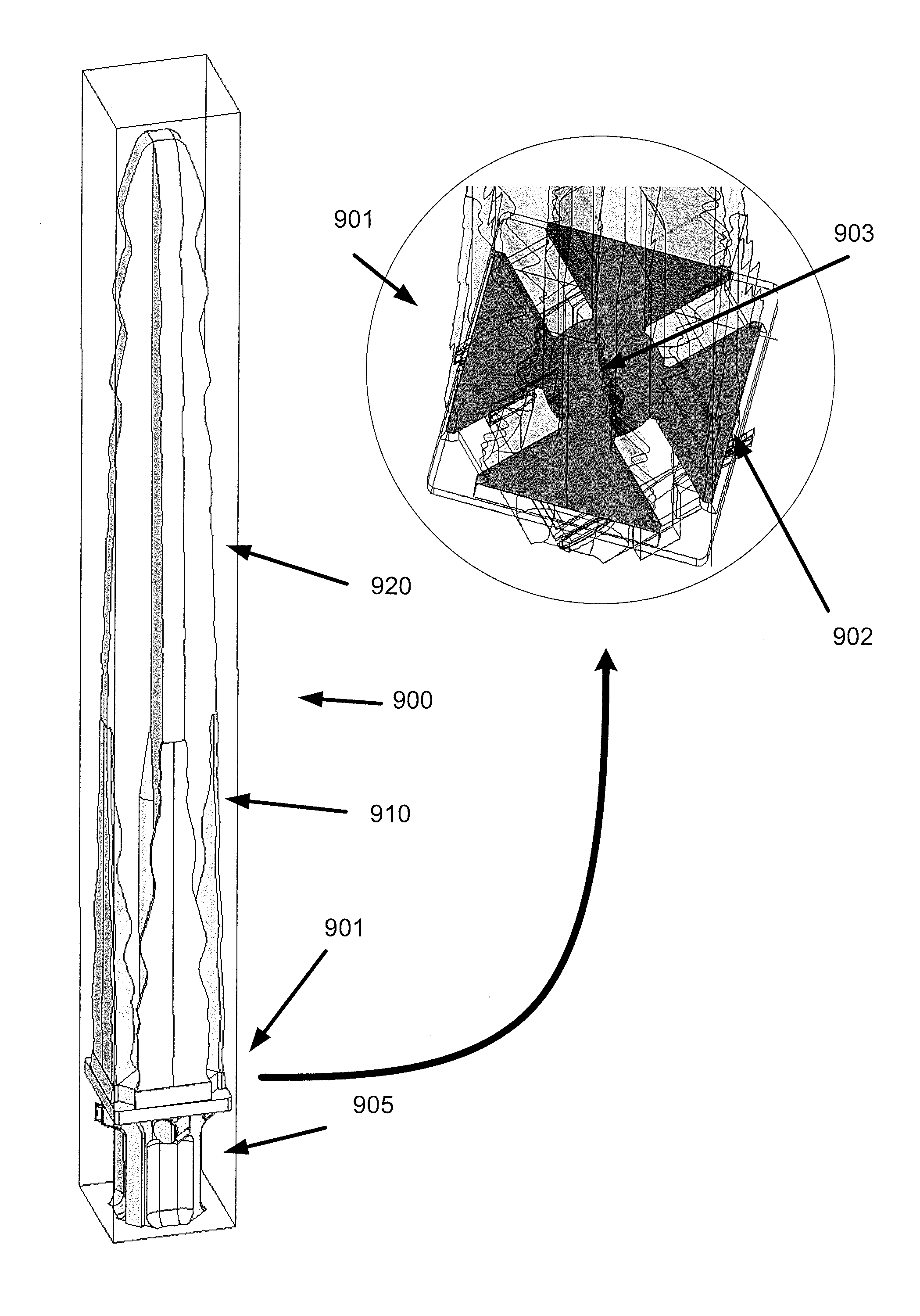
The embodiments described herein are directed to providing a notched antenna element for improving polarization control without sacrificing gain, bandwidth, scan volume, recurring cost, or manufacturability. The notched antenna element includes a base portion comprising a plurality of contiguous first cross-sectional notched antenna elements, each of the plurality of first cross-sectional notched antenna elements configured in an end-loaded structure for increasing polarization stability; and an upper portion coupled to the base portion, the upper portion comprising a plurality of contiguous second cross-sectional notch antenna elements.

Description

CROSS-REFERENCE TO RELATED APPLICATION(S)[0001]This application is an improvement upon and incorporates by reference in its entirety, as if set forth in full, U.S. Pat. No. 6,850,203, filed on Dec. 14, 2001.BACKGROUND[0002]1. Field[0003]Embodiments described herein relate in general to tapered slot antennas and, more particularly, to a method and apparatus for improved D-Plane polarization in such antennas.[0004]2. Description of Related Art[0005]During recent decades, antenna technology has experienced an increase in the use of antennas that utilize an array of antenna elements, one example of which is a phased array antenna. Phased array antennas have many applications in commercial and defense markets, such as communications and radar systems. In many of these applications, broadband performance is desirable. Some of these antennas are designed so that they can be switched between two or more discrete frequency bands. Thus, at any given time, the antenna operates in only one of t...

Claims


Application Information

Patent Timeline
Patent Type & Authority Patents(United States)
IPC IPC(8): H01Q13/10H01Q21/00
CPCH01Q13/085H01Q13/10H01Q21/26H01Q21/06
Inventor REMSKI, RICHARD T.OMMODT, KEVIN W.IRION, II, JAMES M.
Owner RAYTHEON CO
Learn More