Coordinates measuring head unit and coordinates measuring machine

a technology of coordinates and measuring heads, applied in the direction of mechanical diameter measurement, measurement devices, instruments, etc., can solve the problems of inability to detect movement errors of machine tools, high cost of cmms, and large footprint, so as to reduce costs and improve accuracy

Active Publication Date: 2014-02-18
MITUTOYO CORP
View PDF14 Cites 7 Cited by
  • Summary
  • Abstract
  • Description
  • Claims
  • Application Information

AI Technical Summary

Benefits of technology

[0011]The present invention was developed to solve the conventional problems mentioned above. It is therefore an object of the invention to provide a coordinates measuring head unit which is compact, inexpensive, and capable of making measurements at high speeds with high precision, and which facilitates measurements conducted on machine tools or in-situ measurements on transport lines. It is another object of the invention to provide a coordinates measuring machine, a machine tool, and a transport line, which include the coordinates measuring head unit.
[0029]According to the present invention, the coordinates measuring head unit is reduced in measurement stroke and separated from the base and the stand. This allows the head unit to be reduced in size and costs, to make measurements at high speeds with high precision, and to facilitate measurements conducted on machine tools and in-situ measurements on transport lines. In particular, since the measurement stroke is reduced, the head unit can simultaneously implement both high-speed and high-precision measurements, which could not be realized by large CMM's. Furthermore, the head unit can be easily incorporated into machine tools and transport lines (including fabrication lines and inspection lines).
[0031]It is also possible to provide an extremely compact, inexpensive, and high-precision CMM which requires a very small footprint, when the CMM is provided with a base on which a measuring target is placed and a stand for supporting the coordinates measuring head unit on the base.
[0032]Furthermore, a cantilever type stand may be disposed in the direction of depth (the Y-axis direction) when viewed from the front. In this case, the X-axis drive axis can be disposed at the lowest layer most advantageously from the viewpoint of precision in order to minimize the load moving in the lateral direction (the X-axis direction) when viewed from the front.
[0033]Furthermore, the base may also include a table which is to move the measuring target and provided with measuring means for measuring the amount of movement. In this case, works greater than the stroke of the coordinates measuring head unit can also be measured, and thus this can be realized at reduced costs with improved accuracy when compared with the case where the coordinates measuring head unit itself is moved.

Problems solved by technology

There were therefore some problems with those techniques that the CMMs were expensive and needed a large footprint.
This arrangement raised a problem that a movement error of the machine tool could not be detected because the measuring system (guides or scales) of the machine tool was used.

Method used


Image

  • Coordinates measuring head unit and coordinates measuring machine
  • Coordinates measuring head unit and coordinates measuring machine
  • Coordinates measuring head unit and coordinates measuring machine

Examples


Embodiment Construction

[0046]Now, referring to the drawings, an exemplary embodiment of the present invention will be described in more detail.

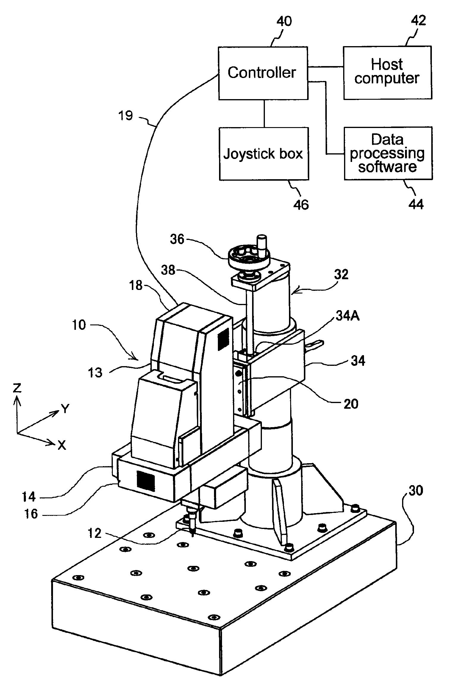
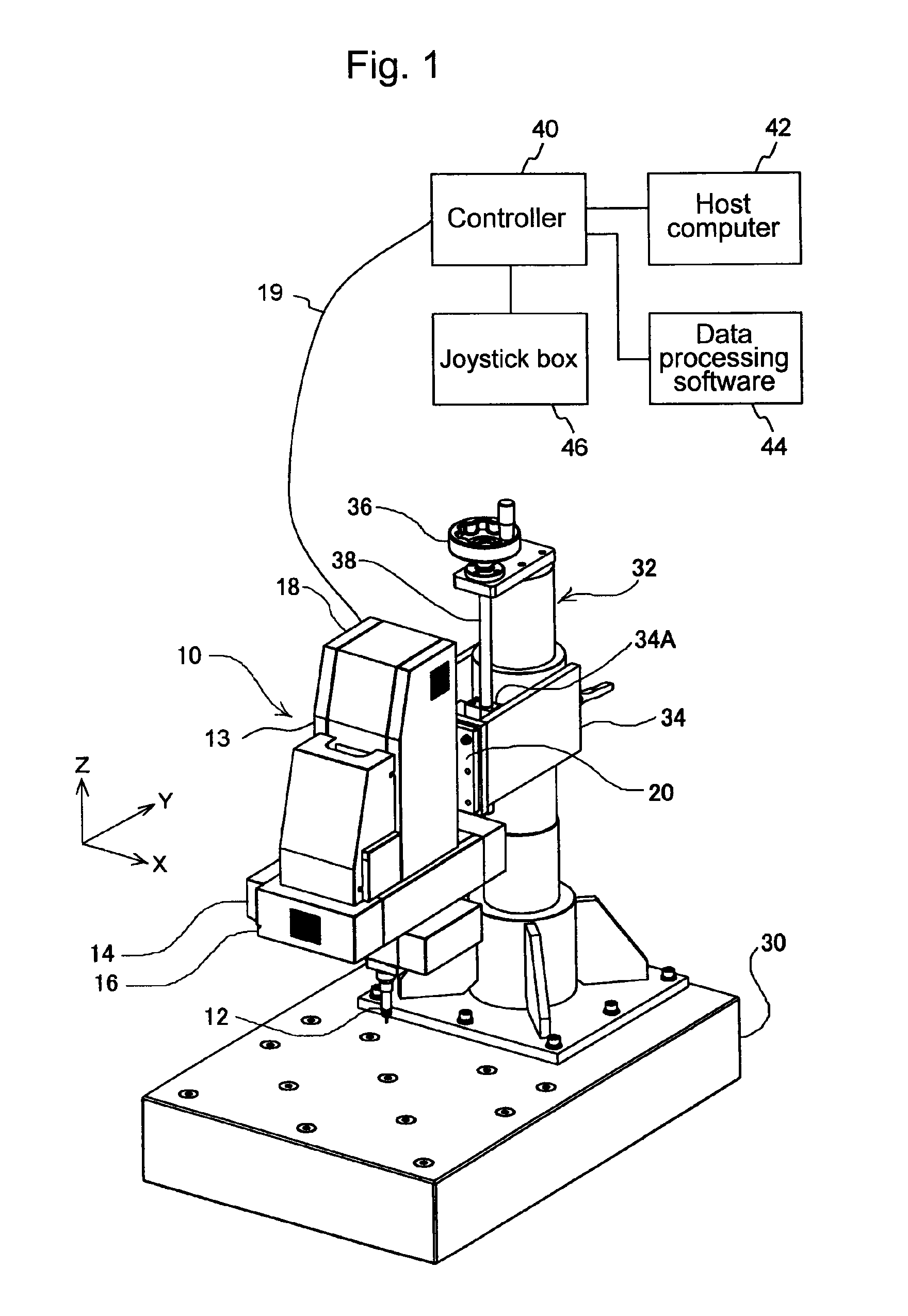
[0047]FIG. 1 illustrates a CMM which is provided with a coordinates measuring head unit according to an exemplary embodiment of the present invention.

[0048]The coordinates measuring head unit 10 according to this exemplary embodiment includes an X-axis drive section 14 for freely moving a probe 12 in the X-axis direction (the right and left direction in the figure), a Y-axis drive section 16 for freely moving the X-axis drive section 14 in the Y-axis direction (the front-to-rear direction in the figure), and a Z-axis drive section 18 for freely moving the Y-axis drive section 16 in the Z-axis direction (the vertical direction in the figure). The head unit 10 also includes an integrated housing 13 for accommodating these sections, and fixture means (here, fixture surface) 20, provided on one of the side surfaces of the housing 13 (here, on the rear surface thereof),...


PUM


Abstract

A coordinates measuring head unit is provided, which is compact, inexpensive, and capable of performing high-precision measurements at high speeds, and facilitates, for example, measurements conducted on machine tools or in-situ measurements on transport lines. The head unit includes: drive means (an X-axis drive section, a Y-axis drive section, and a Z-axis drive section), an integrated housing for accommodating the drive means, and fixture means (fixture surface). The drive means allows a probe to be moved by computer numerical control along a plurality of drive axis, which are orthogonal to each other, and abut against a measuring target to measure the dimensions of the measuring target. The fixture means is provided on one of side surfaces of the housing to attach one of the drive means to a support (a support on a stand secured to a base).

Description

CROSS-REFERENCE TO RELATED APPLICATION[0001]The disclosure of Japanese Patent Application No. 2010-215956 filed on Sep. 27, 2010 including specifications, drawings and claims is incorporated herein by reference in its entirety.BACKGROUND OF THE INVENTION[0002]1. Field of the Invention[0003]The present invention relates to a coordinates measuring head unit and a coordinates measuring machine. More particularly, the invention relates to a coordinates measuring head unit which is compact, inexpensive, and capable of conducting measurements at high speeds with high precision, and facilitates in-situ measurements such as measurements carried out on machine tools or transport lines. The invention also relates to a coordinates measuring machine which incorporates the coordinates measuring head unit.[0004]2. Description of the Related Art[0005]Three-dimensional coordinates measuring machines (hereinafter also referred to as the CMM) are known as a measuring apparatus for measuring three-dim...

Claims


Application Information

Patent Timeline
Patent Type & Authority Patents(United States)
IPC IPC(8): G01B5/008
CPCG01B5/016G01B5/008
Inventor MATSUMIYA, SADAYUKIYOSHIOKA, SUSUMUKAMIYAMA, SHUICHIMIYAZAKI, TOMOYUKIARAI, MASANORI
Owner MITUTOYO CORP
Why Eureka
Try Eureka