Waste toner container and image forming apparatus including same

a technology of image forming apparatus and waste toner container, which is applied in the direction of electrographic process apparatus, instruments, optics, etc., can solve the problems of reducing the replacement cycle of waste toner containers, unable to make full use of the space inside the image forming apparatus, and unable to secure a sufficient capacity of the waste toner container

Active Publication Date: 2014-02-18
RICOH KK
View PDF22 Cites 2 Cited by
  • Summary
  • Abstract
  • Description
  • Claims
  • Application Information

AI Technical Summary

Problems solved by technology

However, if the waste toner container is a substantially rectangular parallelepiped, it is difficult to make full use of the space inside the image forming apparatus and to secure a sufficient capacity of the waste toner container.
Accordingly, replacement cycle of the waste toner container is relatively short.

Method used


Image

  • Waste toner container and image forming apparatus including same
  • Waste toner container and image forming apparatus including same
  • Waste toner container and image forming apparatus including same

Examples


first embodiment

[0034]A first embodiment is described with reference to FIGS. 1 to 16.

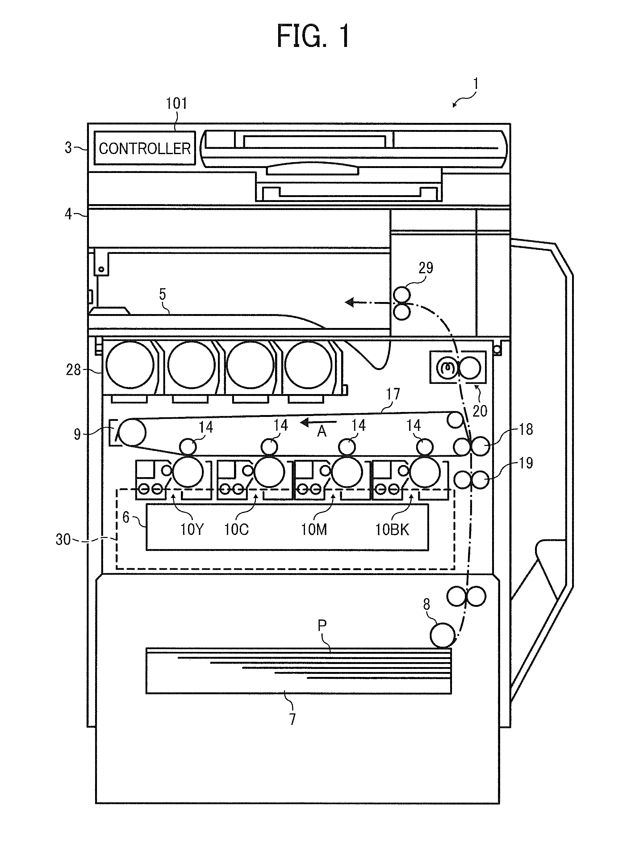
[0035]Referring to FIG. 1, a configuration and operation of an image forming apparatus 1 according to the first embodiment is described below.

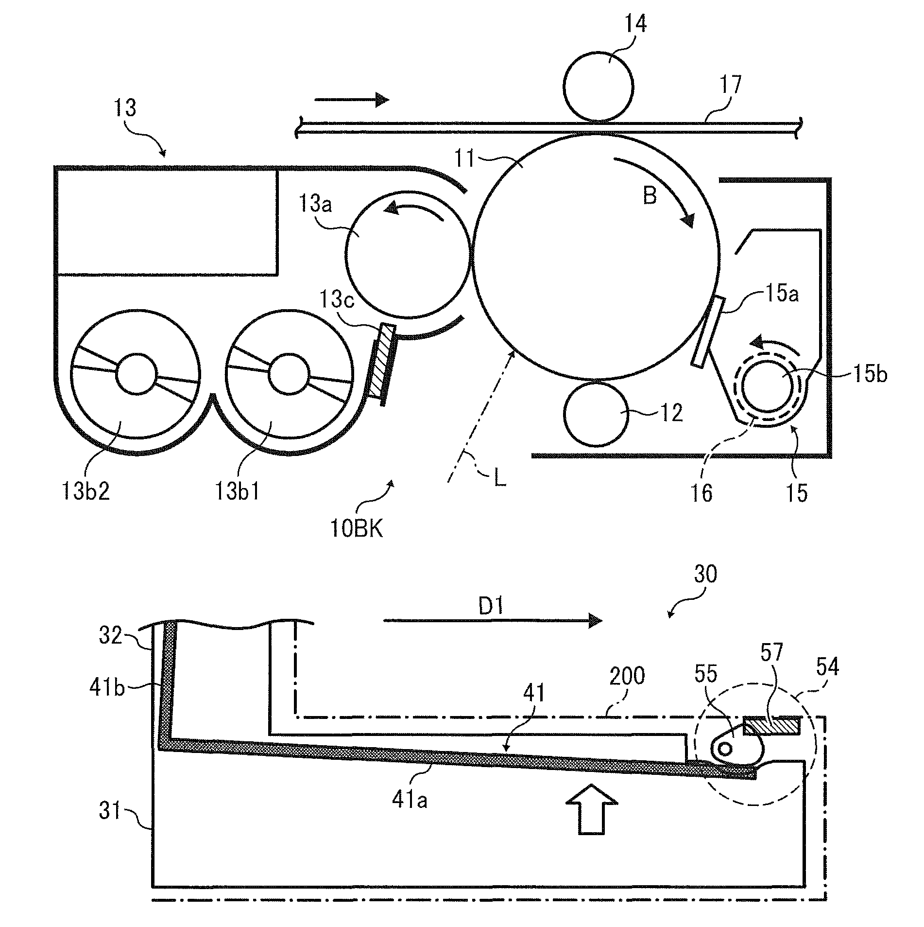
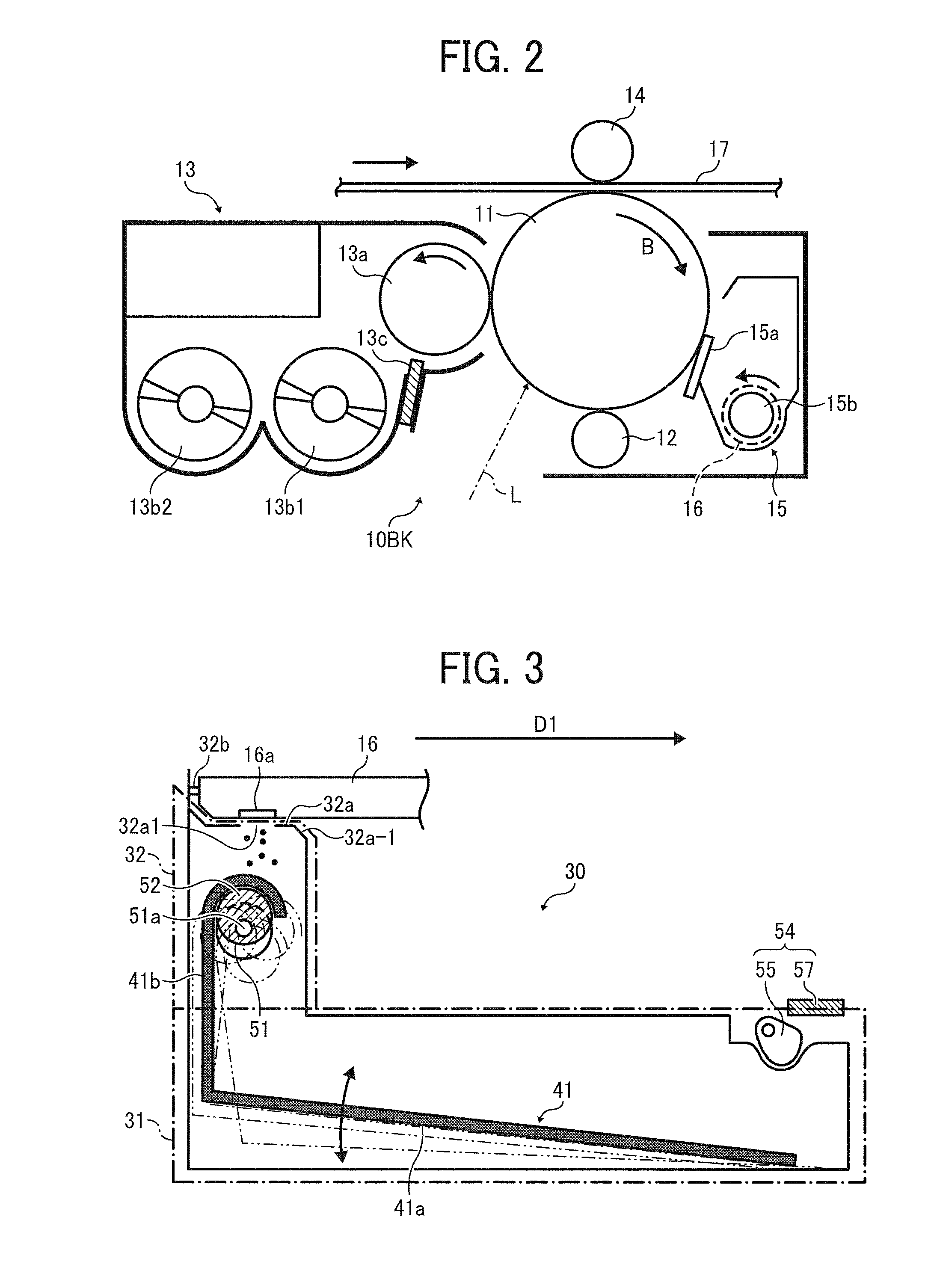
[0036]The image forming apparatus 1 according to the present embodiment is a tandem multicolor image forming apparatus and includes multiple process cartridges 10Y, 10M, 10C, and 10BK, serving as image forming units, that are arranged in parallel to each other, facing an intermediate transfer belt 17 serving as an intermediate transfer member.

[0037]In FIG. 1, reference characters 3 represents a document feeder to send an original document to a document reading unit 4 that reads image data of the original document, 6 represents a writing unit (exposure unit) to emit laser beams L (shown in FIG. 2) according to the image data, 7 represents a sheet feeder for containing sheets P of recording media, 10Y, 10M, 10C, and 10BK represent the process cartridges for respective colors (...

second embodiment

[0150]Referring to FIGS. 17, 18A, and 18B, a second embodiment is described below.

[0151]FIG. 17 is a top view of a waste toner container 30-1 according to the second embodiment and corresponds to FIG. 5 in the above-described first embodiment. FIG. 18A is a schematic view illustrating flow of waste toner adjacent to a waste toner detection unit 54 in the waste toner container 30-1 as viewed from above. FIG. 18B is a schematic view illustrating flow of waste toner adjacent to a waste toner detection unit 54Z in a comparative waste toner container in which a partition is not provided as viewed from above.

[0152]The waste toner container 30-1 is different from that in the first embodiment in that a partition (formed by inner walls defining a recess 31d) is provided adjacent to the waste toner detection unit 54.

[0153]Referring to FIG. 17, similarly to the first embodiment, the waste toner container 30-1 includes a waste toner reservoir 31-1 and a waste toner inlet portion 32, and substan...


PUM


Abstract

A waste toner container includes a waste toner reservoir extending in a depth direction, an inlet portion provided above the waste toner reservoir, in which at least one waste toner inlet is formed, a first conveyance member provided in the waste toner reservoir to transport the waste toner in the depth direction, the first conveyance member movable upward as the amount of the waste toner in the waste toner reservoir increases, a second conveyance member provided in the inlet portion to transport the waste toner in a width direction and including a drive transmitter to transmit a driving force from the second conveyance member to the first conveyance member, and a waste toner detection unit to detect whether an amount of the waste toner in the waste toner container reaches a predetermined amount by detecting upward movement of the first conveyance member.

Description

CROSS-REFERENCE TO RELATED APPLICATIONS[0001]This patent application is based on and claims priority pursuant to 35 U.S.C. §119 to Japanese Patent Application Nos. 2011-059427 filed on Mar. 17, 2011 and 2011-202768 filed on Sep. 16, 2011, in the Japan Patent Office, the entire disclosure of each of which is hereby incorporated by reference herein.FIELD OF THE INVENTION[0002]The present invention relates to an image forming apparatus such as a photocopier, facsimile machine, printer, or multifunction machine having several of those capabilities, and a waste toner container used therein.BACKGROUND OF THE INVENTION[0003]Generally, image forming apparatuses such as copiers and printers include an image bearer, such as a drum-shaped or belt-shaped photoreceptor and a drum-shaped or belt-shaped intermediate transfer member, and a cleaning unit to remove any toner remaining on the image bearer after image transfer. The toner removed from the image bearer (i.e., waste toner) is collected in...

Claims


Application Information

Patent Timeline
Patent Type & Authority Patents(United States)
IPC IPC(8): G03G21/12
CPCG03G21/12
Inventor KARASAWA, SHINYAAMEMIYA, KENOKAMOTO, MICHIYAIWASAKI, TAKUMAAZEYANAGI, YUTAUENISHI, HIROYUKI
Owner RICOH KK
Why Eureka
Try Eureka