

Optical film, antireflection optical element and master
a technology of anti-reflection optical elements and masters, applied in the field of optical elements, optical components having anti-reflection functions, and masters, can solve problems such as insufficient diffraction, and achieve good anti-reflection characteristics
Active Publication Date: 2011-09-29
SONY CORP
View PDF2 Cites 67 Cited by
- Summary
- Abstract
- Description
- Claims
- Application Information
AI Technical Summary
Benefits of technology
[0044]As described above, according to the present invention, an optical element having good anti-reflection characteristics can be provided.
Problems solved by technology
However, when the pitch of the uneven shape is shorter than the wavelength of light transmitted, diffraction is not generated.
Method used
View moreImage
Smart ImageViewing Examples

Examples
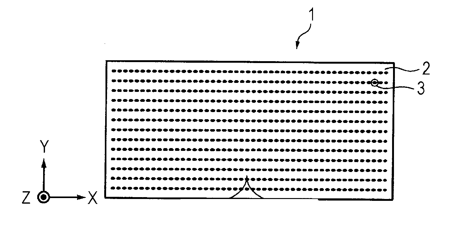
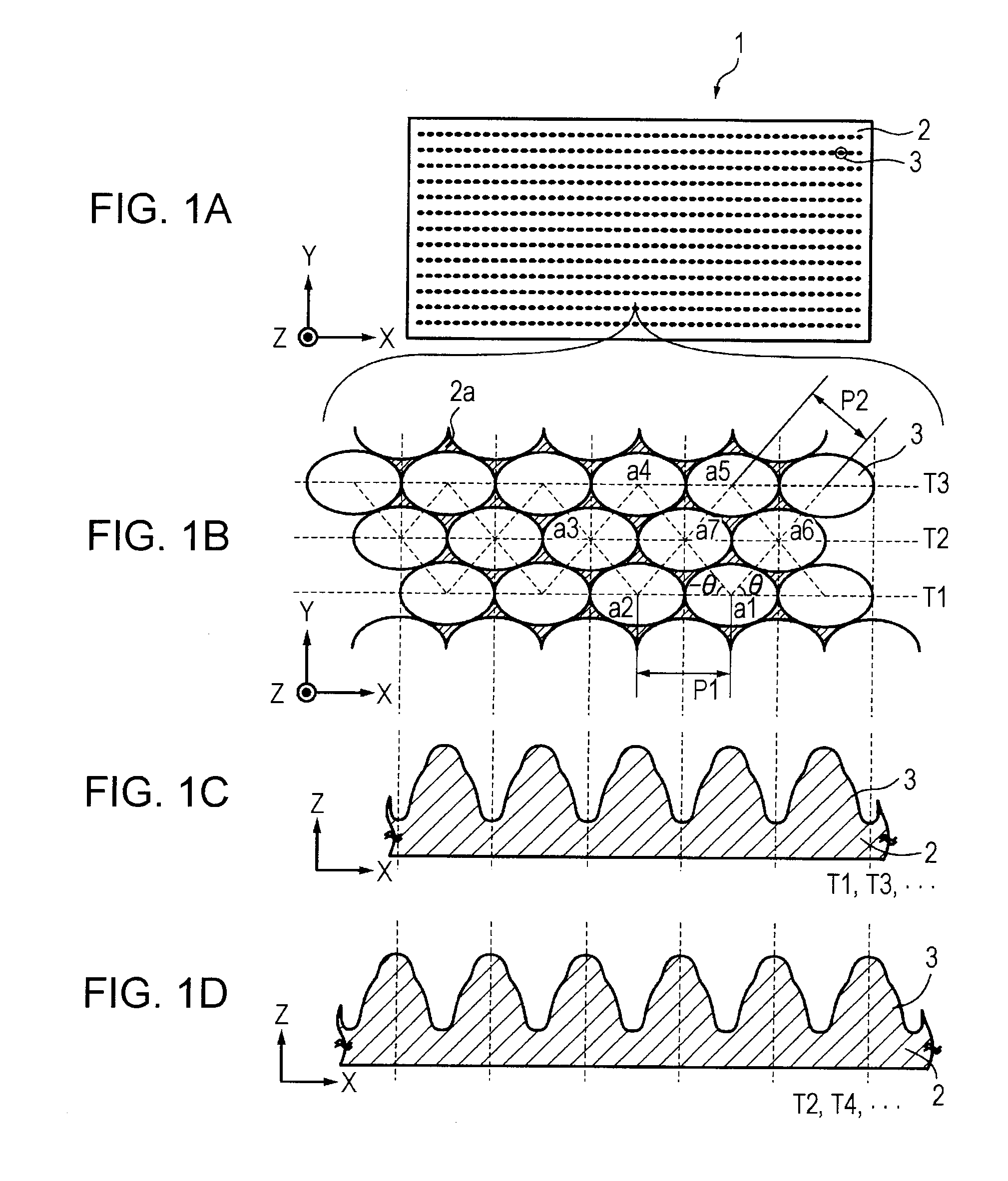
first embodiment (an example in which structures are two-dimensionally arranged linearly in a hexagonal lattice : refer to figs.1a and 1b)
1. First Embodiment (an example in which structures are two-dimensionally arranged linearly in a hexagonal lattice: refer to FIGS. 1A and 1B)
second embodiment (an example in which structures are two-dimensionally arranged in an arc-like shape in a hexagonal lattice : refer to figs.10a and 10b)
2. Second Embodiment (an example in which structures are two-dimensionally arranged in an arc-like shape in a hexagonal lattice: refer to FIGS. 10A and 10B)
third embodiment (an example in which structures are two-dimensionally arranged linearly in a tetragonal lattice : refer to figs.13a and 13b)
3. Third Embodiment (an example in which structures are two-dimensionally arranged linearly in a tetragonal lattice: refer to FIGS. 13A and 13B)
Login to View More PUM
| Property | Measurement | Unit |
|---|---|---|
| Height | aaaaa | aaaaa |
| Refractive index | aaaaa | aaaaa |
| Reflection | aaaaa | aaaaa |
Abstract
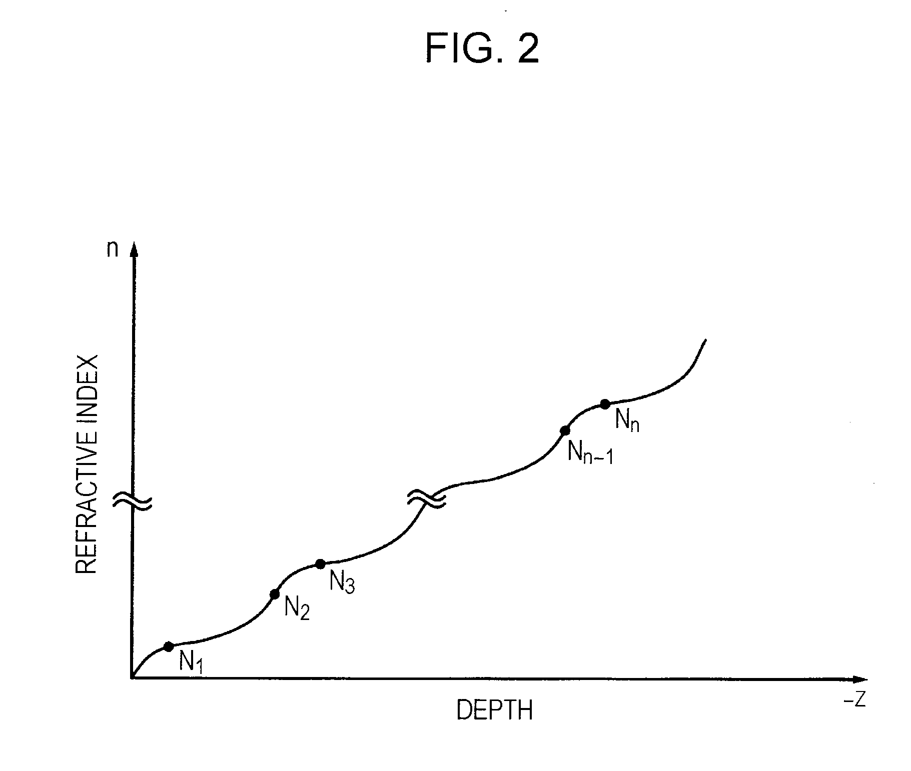
An optical element includes a base and a large number of structures arranged on the surface of the base, the structures being projections or depressions. The structures are arranged at a pitch shorter than or equal to a wavelength of light in a use environment. An effective refractive index in the depth direction of the structures gradually increases toward the base and has two or more inflection points.
Description
TECHNICAL FIELD[0001]The present invention relates to an optical element, an optical component having an anti-reflection function, and a master. Specifically, the present invention relates to an optical element in which structures are arranged at a pitch shorter than or equal to a wavelength of light in a use environment.BACKGROUND ART[0002]Conventionally, in an optical element that uses a light-transmissive substrate composed of glass, plastic, or the like, surface treatment is performed to suppress the surface reflection of light. A method in which a minute and dense uneven structure (moth-eye structure) is formed on the surface of the optical element is exemplified as the surface treatment (e.g., refer to refer to “Optical and Electro-Optical Engineering Contact” Vol. 43, No. 11 (2005), 630-637).[0003]In general, in the case where a periodic uneven shape is formed on the surface of an optical element, diffraction is generated when light passes through the periodic uneven shape, w...
Claims
Login to View More Application Information
Patent Timeline
 IPC IPC(8): G02B27/00G02B1/11G02B1/118
CPCG02B1/118G02F2201/38
InventorHAYASHIBE, KAZUYAENDOH, SOHMEIOIKAWA, MAKIKOKAJIYA, SHUNICHI
OwnerSONY CORP