Power converter designed to enhance stability in operation

a power converter and stability technology, applied in the field of power converters, can solve the problems of increasing the overall size of the power converter, the circuit on the control circuit board is not working properly, etc., and achieves the effect of enhancing the efficiency of cooling the discharging resistor, and reducing the probability of malfunction of the control circuit board

Active Publication Date: 2014-03-04
DENSO CORP
View PDF15 Cites 14 Cited by
  • Summary
  • Abstract
  • Description
  • Claims
  • Application Information

AI Technical Summary

Benefits of technology

[0010]It is therefore an object of this disclosure to provide an improved structure of a power converter which is designed to minimize the risk of a malfunction of an electric circuit fabricated on a control circuit board.

Problems solved by technology

This may cause a portion of the circuit on the control circuit board which is susceptible to heat to be thermally damaged by the discharging resistor 96, which leads to a malfunction of the circuit on the control circuit board 93.
If the discharging resistor is mounted in a converter casing, it will be necessary to increase the volume of the converter casing to secure an installation space for the discharging resistor, thus resulting in an increase in overall size of the power converter.

Method used


Image

  • Power converter designed to enhance stability in operation
  • Power converter designed to enhance stability in operation
  • Power converter designed to enhance stability in operation

Examples


Embodiment Construction

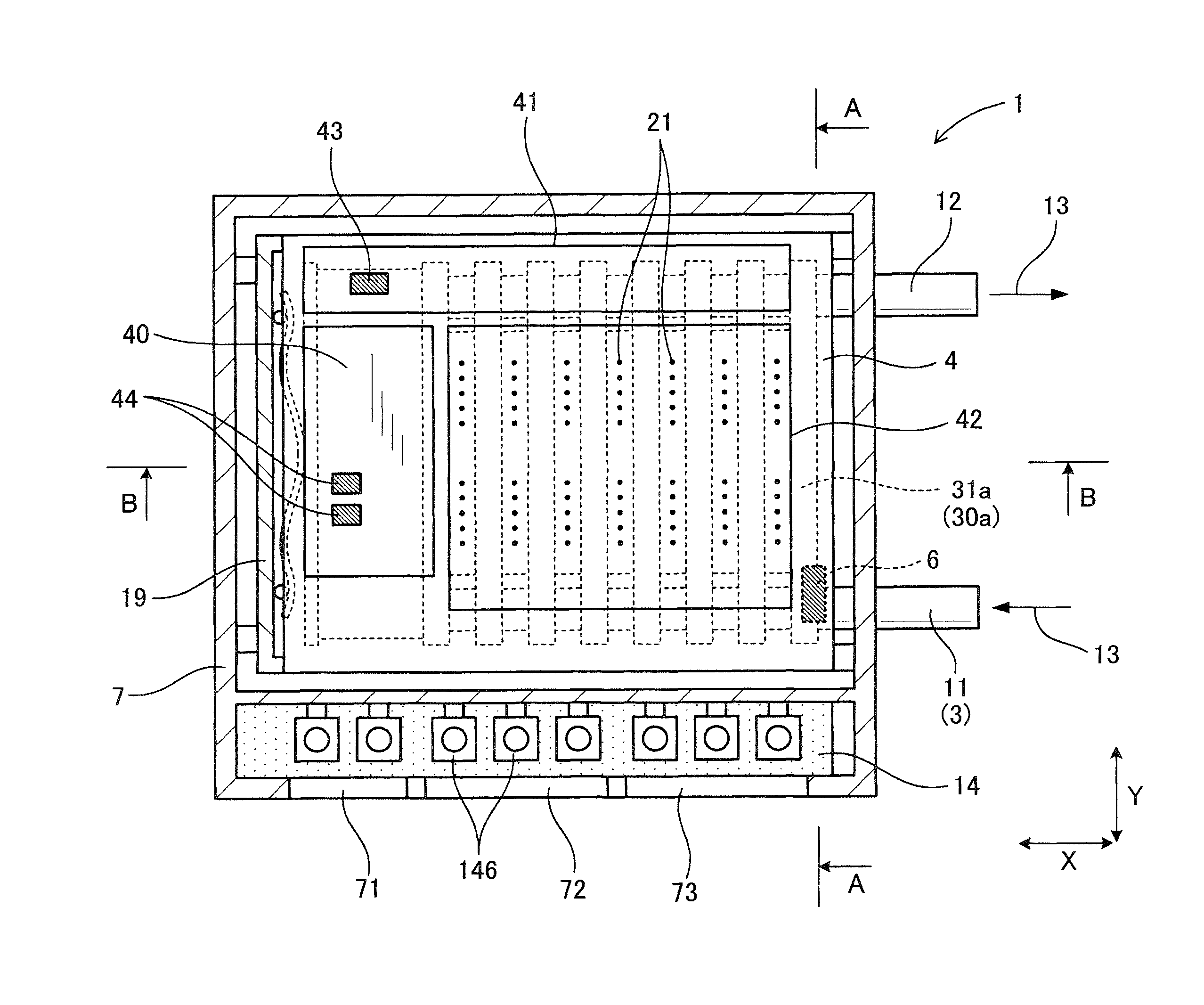
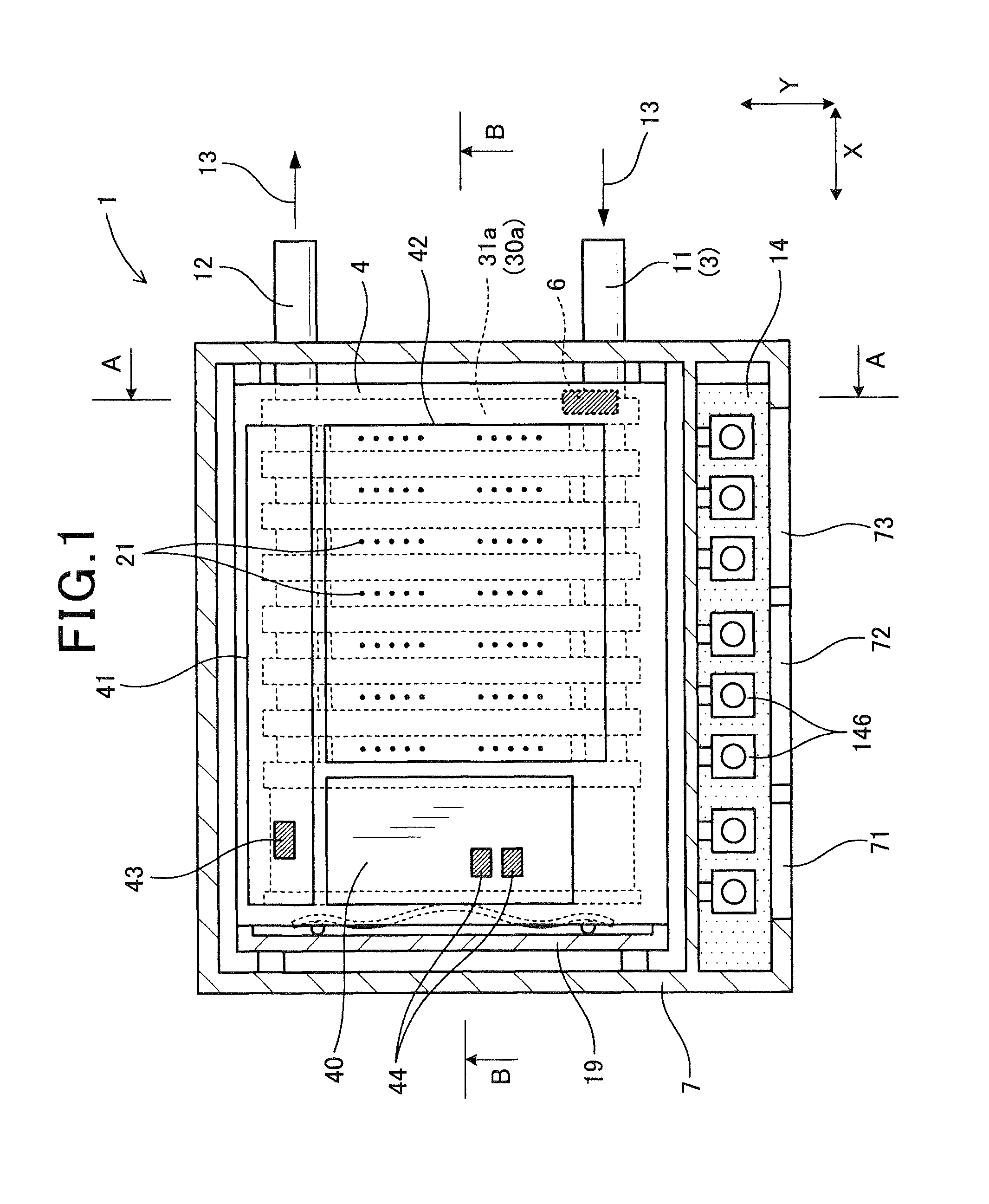
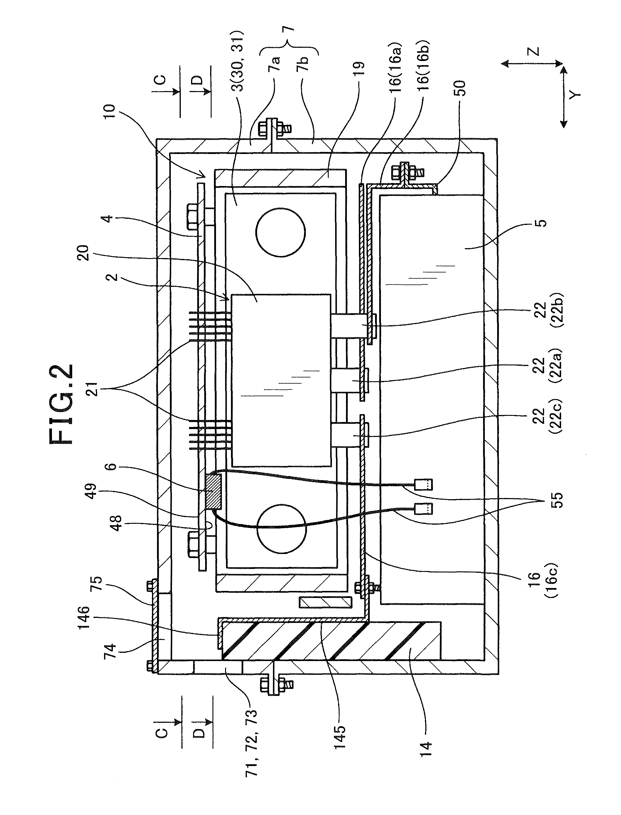
[0036]Referring to the drawings, wherein like reference numbers refer to like parts in several views, particularly to FIGS. 1 to 10, there is shown a power converter 1 which may be mounted in automotive vehicles such as electric vehicles or hybrid vehicles. The power converter 1 is, as illustrated in FIGS. 1 to 4, equipped with a plurality of semiconductor modules 2, a cooling device 3, a smoothing capacitor 5, a control circuit board 4, and a discharging resistor 6. Each of the semiconductor modules 2 includes a main unit 2 in which semiconductor devices, as illustrated in FIG. 6, are fabricated. The main unit 2 has control terminals 21 and power terminals 22 extending therefrom.

[0037]The smoothing capacitor 5 works to smooth the DC voltage applied to the semiconductor modules 2.

[0038]The control circuit board 4 has fabricated thereon a control circuit, as will be described later in detail, which controls on / off operations of the semiconductor modules 2 in a conventional manner.

[00...


PUM


Abstract

A power converter equipped with a plurality of semiconductor modules, a cooling device, a control circuit board, a smoothing capacitor, and a discharging resistor. The discharging resistor mounted on the control circuit board in parallel connection to the smoothing capacitor. The control circuit board has fabricated thereon a timing controller working to control timings of on / off operations of the semiconductor modules, a driver coupled to control terminals of the semiconductor modules to control voltage applied to the control terminals, and a power supply circuit working to transform a voltage input to the control circuit board into operating voltages for the timing controller and the driver. The driver is disposed between at least one of the timing controller and the power supply circuit and the discharging resistor, thereby protecting the timing controller and / or the power supply circuit mounted on the control circuit board from thermal energy radiating from the discharging resistor.

Description

CROSS REFERENCE TO RELATED DOCUMENT[0001]The present application claims the benefit of priority of Japanese Patent Application No. 2011-203975 filed on Sep. 19, 2011, the disclosure of which is incorporated herein by reference.BACKGROUND[0002]1. Technical Field This application relates generally to a power converter which is equipped with a discharging resistor and designed to enhance the stability in operation thereof.[0003]2. Background Art[0004]Power converters are known which work to perform power conversion between DC power and AC power and are equipped with a smoothing capacitor and a discharging resistor for releasing electric charge stored in the smoothing capacitor. For instance, Japanese Patent First Publication Nos. 2010-124523 and 11-235043 teach such a type of power converter. FIG. 13 illustrates an example of a conventional power converter.[0005]The power converter 9 consists of a plurality of semiconductor modules 90 in which semiconductor devices are installed. Each ...

Claims


Application Information

Patent Timeline
Patent Type & Authority Patents(United States)
IPC IPC(8): H02M1/00
CPCH02M2001/007H02M7/003H02M2001/008H05K7/20927H02M1/007H02M1/008
Inventor SUZUKI, TOMOTAKAMAEBARA, TSUNEO
Owner DENSO CORP
Why Eureka
Try Eureka