
Unidirectional asymmetric traffic pattern systems and methods in switch matrices

a traffic pattern and switch matrix technology, applied in data switching networks, multiplex communication, digital transmission, etc., can solve the problems of fragmentation and/or loss of bandwidth, inability to merge these connections into one manageable connection, and automatically becoming unusable in the other direction

Active Publication Date: 2014-03-04
CIENA
View PDF23 Cites 5 Cited by
  • Summary
  • Abstract
  • Description
  • Claims
  • Application Information

AI Technical Summary

Problems solved by technology

Disadvantageously, if only one direction is used, the other direction automatically becomes unusable.
Conventional abstraction systems and methods have bandwidth fragmentation and / or loss of bandwidth whenever there is a need to have instances of asymmetric traffic patterns.
Because a true asymmetric pattern is not possible to have as described herein, the conventional abstraction systems and methods leave out the bandwidth in an opposite direction as unusable and configure / provision the next set of timeslots for different concatenation.
Further, assume two different connections in a switch, e.g. symmetric or asymmetric with drops and continues, and assume these two different connections belong to different end users, it is not possible conventionally to merge these connections into one manageable connection without hitting traffic and without affecting blocking probability of a switch fabric.
Thus, conventional abstraction systems and methods do not allow one traffic pattern to be converted to another without deleting and re-creating, e.g. conversion from symmetric to asymmetric and vice-versa.
Conventional abstraction systems and methods do not provide a way for merging and splitting traffic patterns between two different end users within a single network element without affecting traffic and also without affecting the blocking probability.
They may re-work the connections but do not guarantee that the connections pass through the same exact center stage for every flow from begin to end and thus causing an increased blocking probability.

Method used


Image

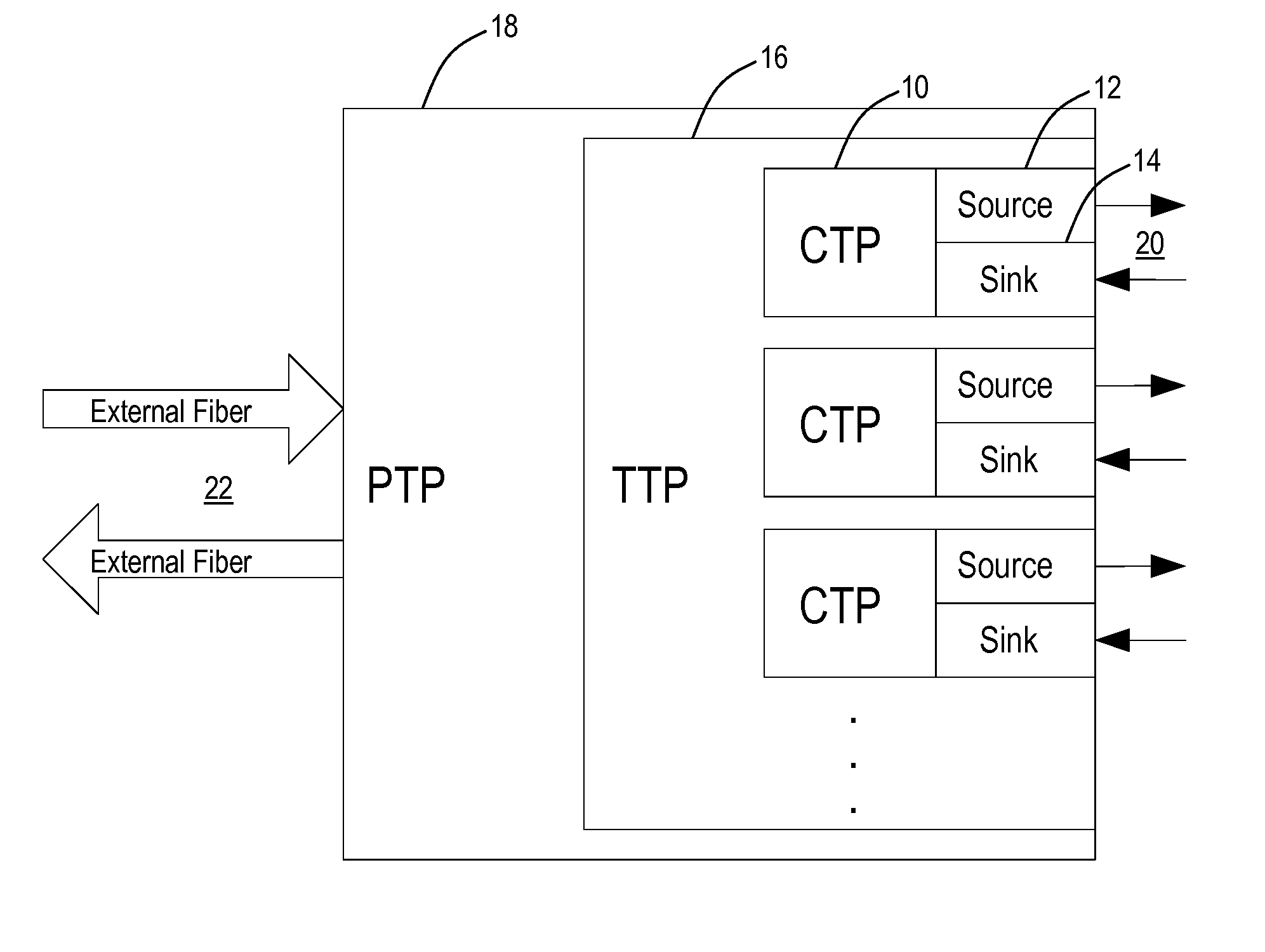
  • Unidirectional asymmetric traffic pattern systems and methods in switch matrices
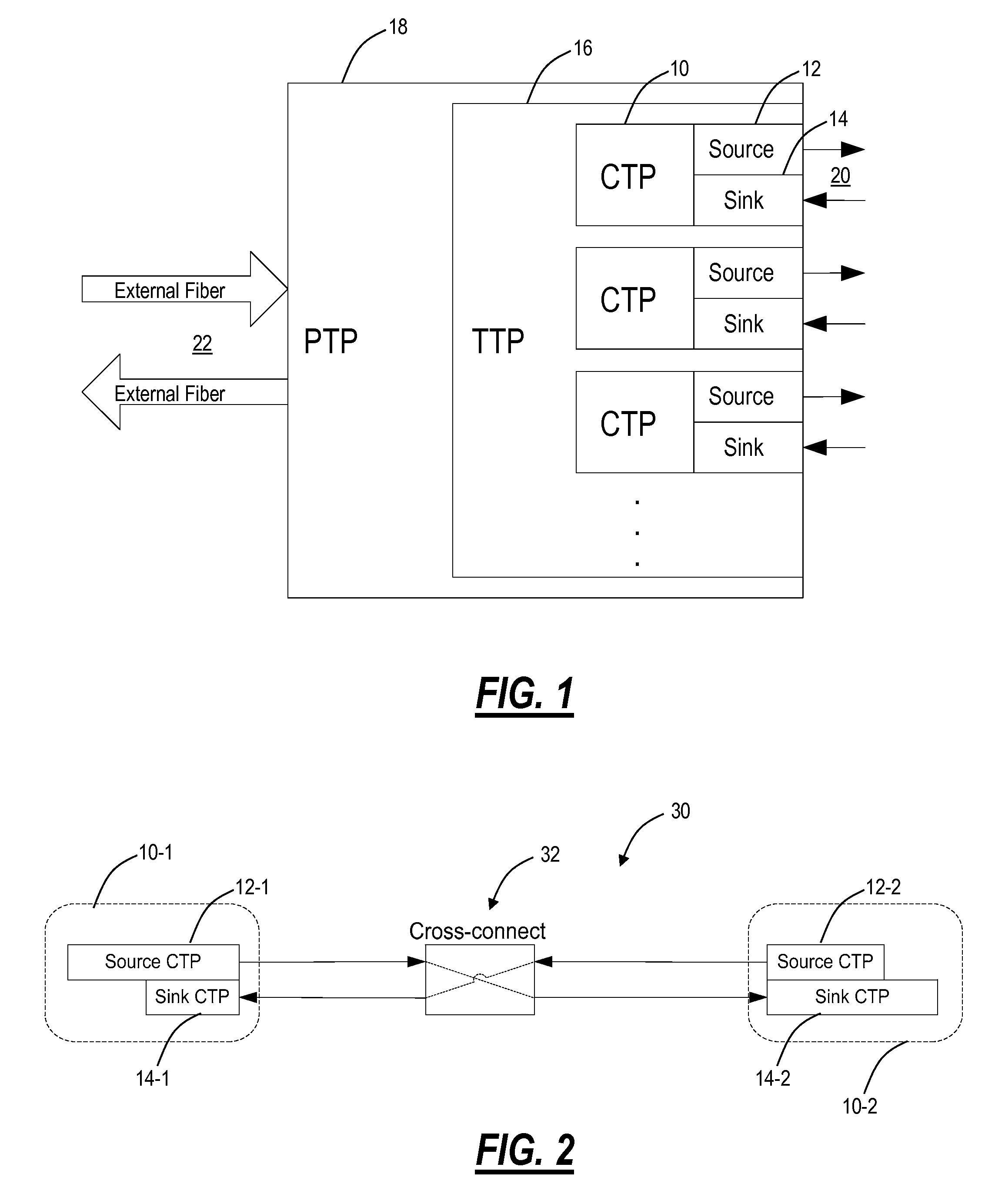
  • Unidirectional asymmetric traffic pattern systems and methods in switch matrices
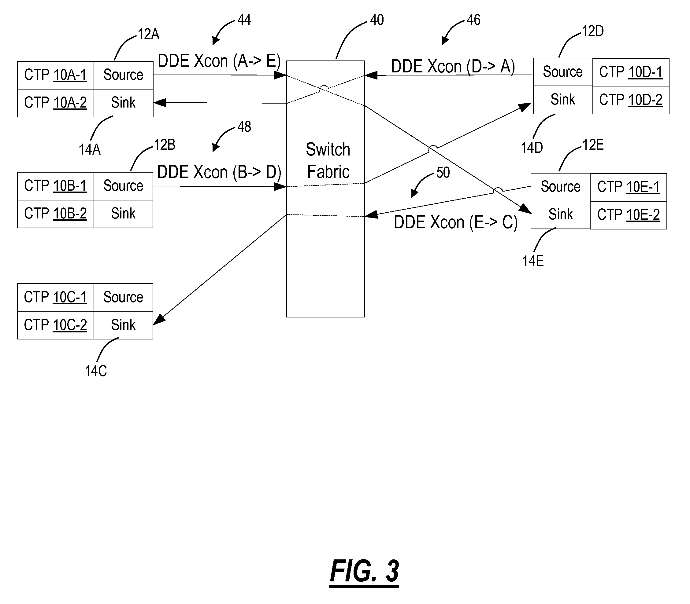
  • Unidirectional asymmetric traffic pattern systems and methods in switch matrices

Examples


Embodiment Construction

[0026]In various exemplary embodiments, the present disclosure relates to unidirectional asymmetric traffic pattern systems and methods in switch matrices, network elements, and networks based thereon. In particular, the systems and methods include switch fabrics, network elements, methods, and networks based thereon using an information model such as ITU-T M.3100 or variants thereof to manage physical connections therein. To address limitations associated with symmetric traffic patterns between transmit and receive directions, the systems and methods include asymmetric traffic patterns in the switch matrices, network elements, and networks based thereon. In particular, the systems and methods include a flexible way for overlapping two different size cross connects and / or FCCs in transmit and receive directions seamlessly. To address limitations associated with merging and splitting traffic patterns, the systems and methods utilize Virtual Connection Point (VCP) merges and splits. F...


PUM


Abstract

A switch fabric system and network element based thereon include a N×M switch fabric with M Trail Termination Points (TTPs) each with N timeslots there through in a bidirectional manner, a first connection in the switch fabric, wherein the first connection includes a unidirectional asymmetric connection of X timeslots, wherein X<N, and a second connection in the switch fabric in an opposite direction as the first connection, wherein the second connection includes a unidirectional asymmetric connection of Y timeslots, wherein Y<N, and wherein at least one of the Y timeslots overlaps with one of the X timeslots on a same TTP of the M TTPs, wherein N, M, X, and Y each include an integer. A method includes establishing unidirectional asymmetric connections with overlapping portions therein as well as merging, splitting, and converting connections in-service and minimizing blocking probabilities.

Description

FIELD OF THE INVENTION[0001]Generally, the field of art of the present disclosure pertains to communication networks, and more particularly, to unidirectional asymmetric traffic pattern systems and methods in switch matrices, network elements, and networks based thereon.BACKGROUND OF THE INVENTION[0002]Conventionally, in communication networks, switches can be managed through abstract models. For example, cross connects in a switching fabric can be managed based on abstractions in software consistent with standards defined by the International Telecommunications Union (ITU) and Telecordia standards bodies. One such standard is ITU-T M.3100 “Generic network information model” (April 2005), the contents of which are incorporated by reference herein. In operation, the abstractions are used to manage physical connections in an actual switch. That is, the abstractions represent logical software objects managing real connections in hardware. Conventional abstraction systems and methods al...

Claims


Application Information

Patent Timeline
Patent Type & Authority Patents(United States)
IPC IPC(8): H04L12/46
CPCH04J2203/0003H04J2203/0098H04J2203/0055H04J3/1611H04J3/1652
Inventor GOPALAKRISHNA, SATISHCHAKRABARTY, MONALIFREESTONE, BRYAN
Owner CIENA
Learn More