Method for data path creation in a modular lighting system

a data path and modular lighting technology, applied in the field of modular lighting, can solve the problems of defunct or inefficient already established data paths, inability to meet the needs of external controllers, and inability to know the geometric shape and/or size of the modular lighting system in general, so as to reduce power consumption

Inactive Publication Date: 2014-03-11
KONINK PHILIPS ELECTRONICS NV
View PDF8 Cites 0 Cited by
  • Summary
  • Abstract
  • Description
  • Claims
  • Application Information

AI Technical Summary

Benefits of technology

[0011]By such a method, there is provided a modular lighting system that can enable forming in general one data path from the control device of the lighting system to each lighting module in the lighting system that is the shortest possible route from the control device to the lighting module. In such a data path, lighting data, control data, etc., may be forwarded to the lighting module in a serial fashion. Such a method may advantageously be performed at the start-up (power-up) of the modular lighting system, such that optimal data paths with regards to control signal path-length for lighting modules of the system may be formed and utilized during subsequent operation of the lighting system. In this manner, such a method can enable communication of data, such as data related to luminance, color, etc., to individual light-emitting elements (e.g. LEDs) of a lighting module in an optimal manner with regards to data path length from the control device to the lighting module.
[0018]By a lighting system according to the second aspect of the present invention, advantages similar to or the same as the advantages of the method according to the first aspect of the present invention may be achieved.
[0024]Such a configuration may enable data path creation to be re-executed in case a lighting module detects loss of received data, for the particular lighting module only, without having to go through the data path creation process for the entire lighting system. This may involve disabling the output of all communication units of the particular lighting module, whereby further lighting modules may be forced to re-establish a new data source.
[0033]According to yet another embodiment of the present invention, each of the optimal control signal data paths may be further adapted to communicate data from the respective lighting module to the control device, thereby forming a data return path.
[0035]The temporal density of data that is returned to the control device from the lighting modules via such data return paths may increase as the distance to the control device decreases. To this end, lighting modules may be adapted to reduce data collision and overflow, for example by means of temporal data storage units comprised e.g. in the communication units of the respective lighting modules.
[0041]In this manner, the need for the lighting modules (or communication units) to be in state of actively listening to detect the occurrence of control signal may be mitigated or eliminated, as each of the communication units may postpone listening to detect the occurrence of control signals until the communication unit has detected receipt of a control signal anticipation signal. In this manner, power consumption may be reduced compared to a case where communication units constantly are in a state of actively listening to detect the occurrence of control signals.

Problems solved by technology

However, the geometric shape and / or size of the modular lighting system is in general unknown to the external controller at power-up of the lighting system.
Moreover, the geometric shape and / or size of the modular lighting system may change during operation of the lighting system, whereby already established data paths may be rendered defunct or inefficient (i.e. not optimal with regards to data path length from the external controller to a particular module).

Method used


Image

  • Method for data path creation in a modular lighting system
  • Method for data path creation in a modular lighting system
  • Method for data path creation in a modular lighting system

Examples


Embodiment Construction

[0053]The present invention will now be described more fully hereinafter with reference to the accompanying drawings, in which exemplifying embodiments of the invention are shown. This invention may, however, be embodied in many different forms and should not be construed as limited to the embodiments set forth herein; rather, these embodiments are provided by way of example so that this disclosure will be thorough and complete, and will fully convey the scope of the invention to those skilled in the art. Furthermore, like numbers refer to like or similar elements throughout.

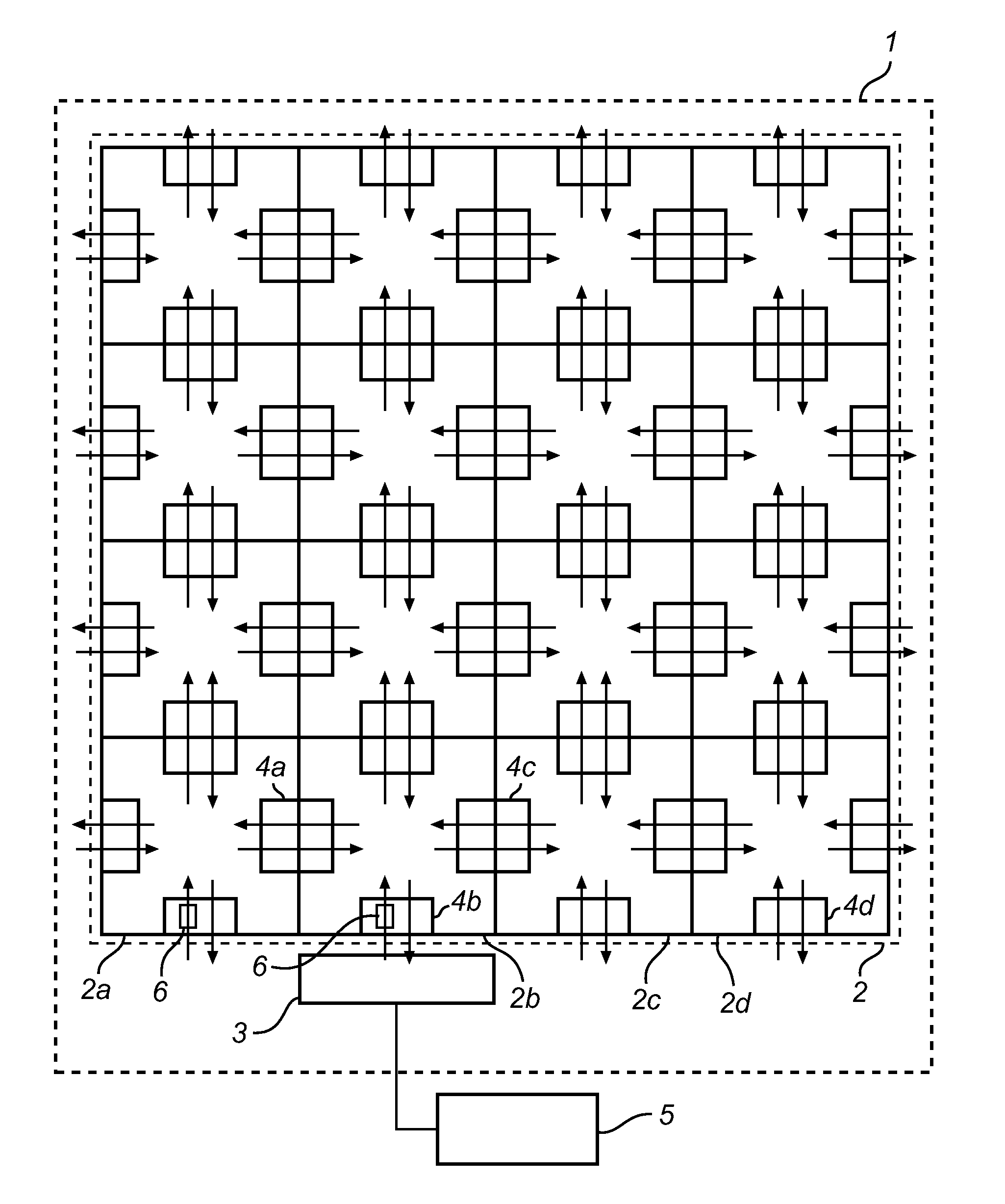
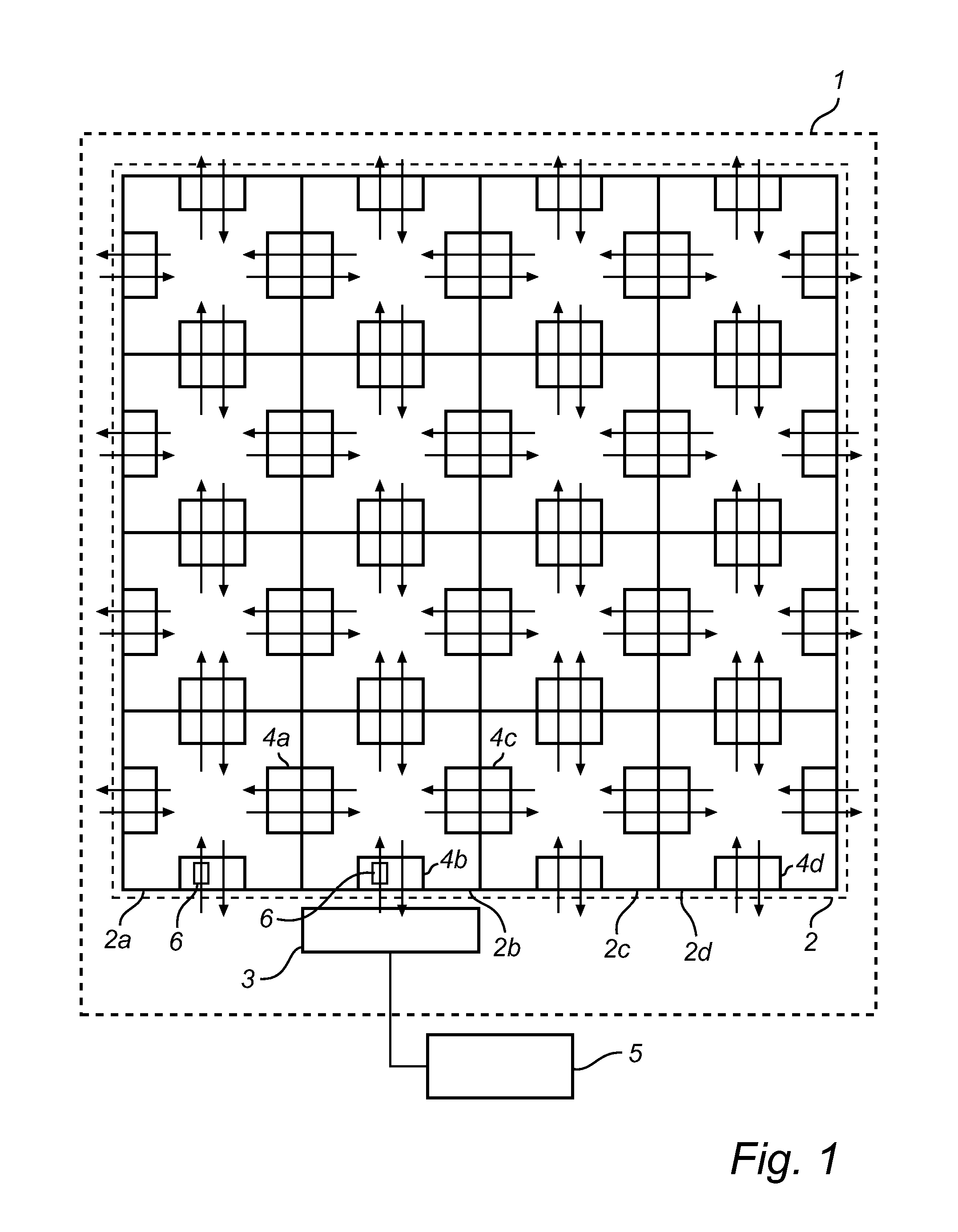
[0054]Referring to FIG. 1, there is shown a schematic view of a modular lighting system 1 according to an exemplifying embodiment of the present invention, comprising a plurality 2 of lighting modules 2a, 2b, 2c, 2d, . . . and a control device 3. Each of the lighting modules 2a, 2b, 2c, 2d, . . . (of which only a few are indicated by reference numerals in FIG. 1) may comprise a plurality of communication units 4...


PUM


Abstract

It is disclosed a method for operating a lighting system, which lighting system comprises a plurality of lighting modules, each of which comprises at least one communication unit, via which the respective lighting module is adapted to communicate with at least one neighboring lighting module. A control device may be adapted to communicate control signals to at least one of the lighting modules and each of the lighting modules may be adapted to further communicate control signals communicated to the lighting module to a neighboring lighting module. The method comprises assigning a communication unit of each of a plurality of lighting modules to be an active communication unit associated with a minimum control signal path length value with respect to all of the communication units of the lighting module, as measured from the control device to the communication unit, whereby optimal control signal data paths, each data path being adapted to communicate control signals from the control device to a lighting module, may be formed. It is further disclosed a lighting system adapted to perform the method.

Description

FIELD OF THE INVENTION[0001]The present invention generally relates to the field of modular lighting. In particular, the present invention is related to a method for operating a modular lighting system.BACKGROUND OF THE INVENTION[0002]Light-emitting diodes (LEDs) intended for indication purposes have been used for a long time, but high-brightness LEDs, e.g. LEDs having a brightness that is high enough to enable general illumination of various locations such as rooms, have in a short period of time caused a significant growth in the LED and lighting applications market. High brightness LEDs are generally associated with a small size, a relatively high efficacy (and associated low temperature), a relatively long lifetime, a wide color gamut and ease of control. Naturally, such LEDs are of importance to lighting designers in developing new lighting applications. Such LEDs may also be utilized in replacing conventional light generation devices, such as filamented light bulbs or halogen ...

Claims


Application Information

Patent Timeline
Patent Type & Authority Patents(United States)
IPC IPC(8): H05B37/00
CPCH05B37/0254H05B47/18
Inventor SNIJDER, PIETER JACOBSONNEVILLE, PIERRE ROBERT VALERE
Owner KONINK PHILIPS ELECTRONICS NV
Why Eureka
Try Eureka