Stretch liner clamp

Active Publication Date: 2014-03-18
PACHECO MARTIN I +1
View PDF8 Cites 9 Cited by
  • Summary
  • Abstract
  • Description
  • Claims
  • Application Information

AI Technical Summary

Benefits of technology

[0008]In addition, the present invention includes a method for assisting a bricklayer or mason worker in positioning and aligning a next row of bricks being laid upon a previous row of bricks using an alignment string. One end of the alignment string is secured in a desired position adjacent the previous row of bricks. The method comprises providing a clamp having a first clamp arm a

Problems solved by technology

Due to the precision needed, corner leads are time-consuming to erect and require the skills of experienced bricklayers.
Unfort

Method used


Image

  • Stretch liner clamp
  • Stretch liner clamp

Examples


Embodiment Construction

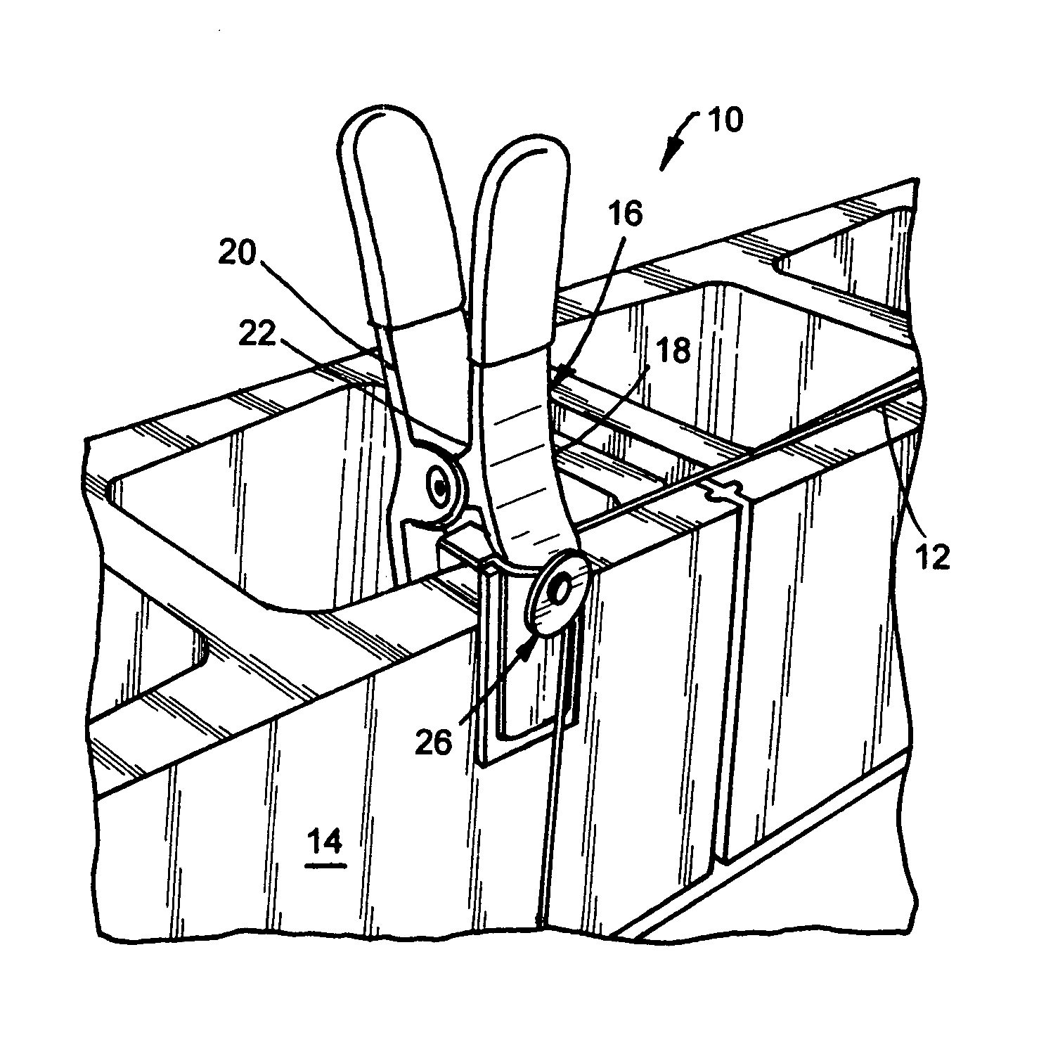
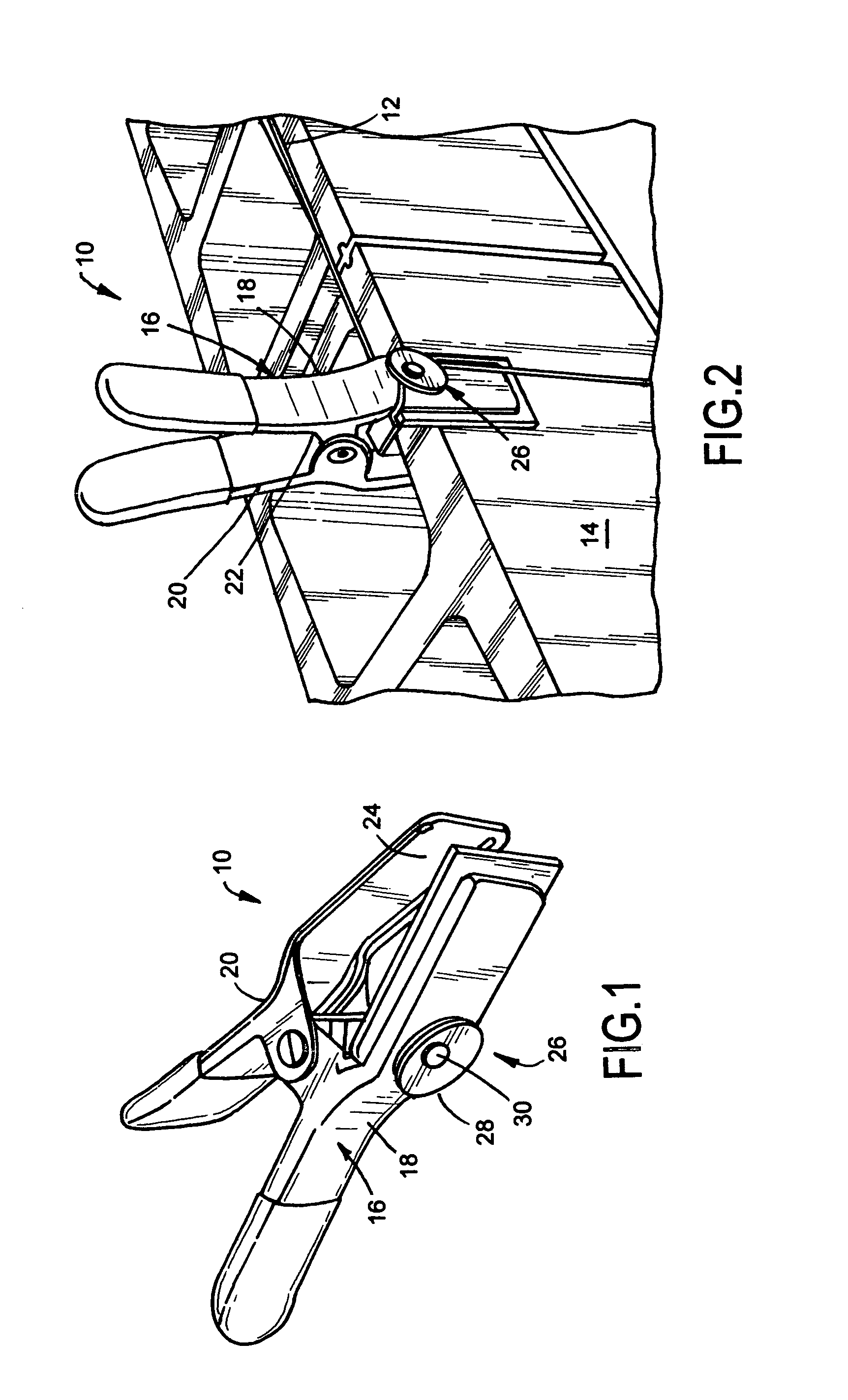
[0012]As illustrated in FIGS. 1 and 2, the present invention is a stretch liner clamp, indicated generally at 10, for facilitating attachment of an alignment string 12 and positioning the alignment string 12 in the exact alignment desired by the bricklayer or mason for the row of bricks 14 being laid. The stretch liner clamp 10 of the present invention assists bricklayers and masons in laying bricks 14 in a precise and accurate manner.

[0013]The stretch liner clamp 10 of the present invention comprises a clamp 16 having a first clamp arm 18 and a second clamp arm 20. A spring mechanism 22 biases the first clamp arm 18 and the second clamp arm 20 together and each clamp arm 18, 20 can preferably have a hard rubber pad 24 at the clamping end to protect the item to which the clamp 16 is applied. Preferably, the clamp 16 is an A-type spring clamp, approximately seven (7″) inches in height and approximately five (5″) inches in width although utilizing other types of clamps having differen...


PUM


Abstract

A clamp mechanism for assisting a bricklayer or mason worker in positioning and aligning a next row of bricks being laid upon a previous row of bricks using an alignment string is provided. One end of the alignment string is secured in a desired position adjacent the previous row of bricks. The clamp mechanism comprises a clamp having a first clamp arm and a second clamp arm. A spring mechanism biases the first clamp arm and the second clamp arm in a general direction toward each other. A string receiving mechanism is associated with the clamp for receiving a portion of the alignment string. Upon the alignment string being secured to the string receiving mechanism and the clamp being positioned upon a brick in the previous row of bricks, the alignment string indicates the proper positioning and alignment of the next row of bricks.

Description

[0001]The present application claims the benefit of priority of pending provisional patent application Ser. No. 61 / 337,473, filed on Feb. 4, 2010, entitled “Stretch liner clamp”.BACKGROUND OF THE INVENTION[0002]1. Field of the Invention[0003]This invention relates generally to a stretch liner clamp and, more particularly, the invention relates to a stretch liner clamp for facilitating attachment of the alignment string and positioning the string in the exact alignment desired by the bricklayer for the row of bricks being laid.[0004]2. Description of the Prior Art[0005]When building a structure, brick masons use one of two methods, either the corner lead or the corner pole. Using the corner lead method, they begin by constructing a pyramid of bricks at each corner called a lead. After the corner leads are complete, less experienced brick masons fill in the wall between the corners using a line from corner to corner to guide each course, or layer, of brick. Due to the precision needed...

Claims


Application Information

Patent Timeline
IPC IPC(8): B25B5/00
CPCB25B5/06B25B5/00Y10T29/539
Inventor PACHECO, MARTIN I.CRUZ, CESAR
Owner PACHECO MARTIN I
Why Eureka
Try Eureka