
Method for increasing the time for illumination of targets by a secondary surveillance radar

a secondary surveillance and radar technology, applied in the direction of reradiation, measurement devices, instruments, etc., can solve the problems of limited effective interrogation arc of radar (1030 mhz), limited use of signals in transmission and reception, and incompatibility with operational limitations

Active Publication Date: 2014-03-18
THALES SA
View PDF14 Cites 31 Cited by
  • Summary
  • Abstract
  • Description
  • Claims
  • Application Information

AI Technical Summary

Benefits of technology

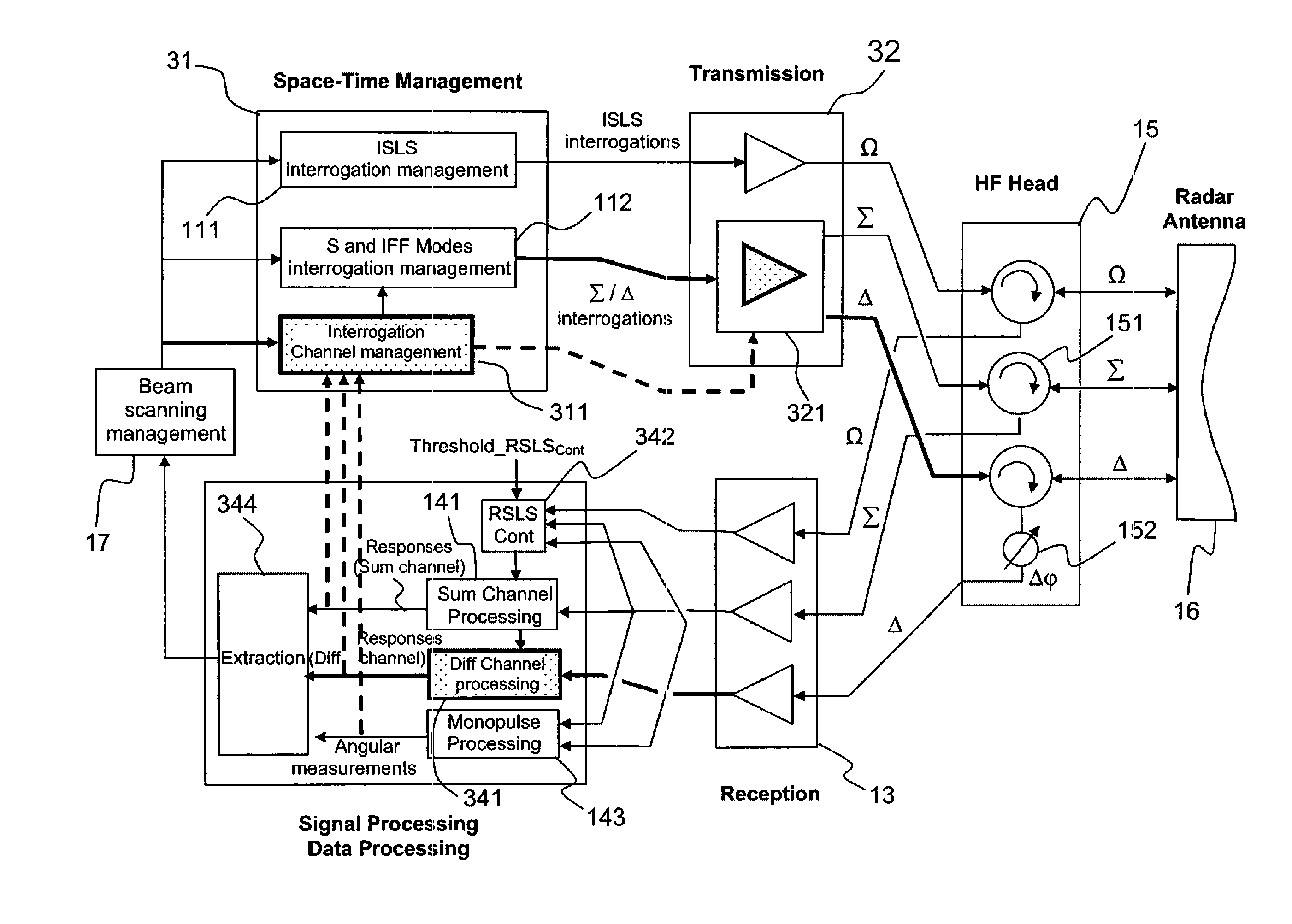
[0036]One aim of the invention is to solve the aforementioned problems by providing a substantial increase, even a doubling, of the illumination time of a target of a secondary surveillance radar with rotating antenna in each spatial direction. Another aim of the invention consists in providing this increase without the necessity for substantial modification of the structure of the radar and, in particular, without requiring modification of either the antenna or of the means of formation of the channels.

Problems solved by technology

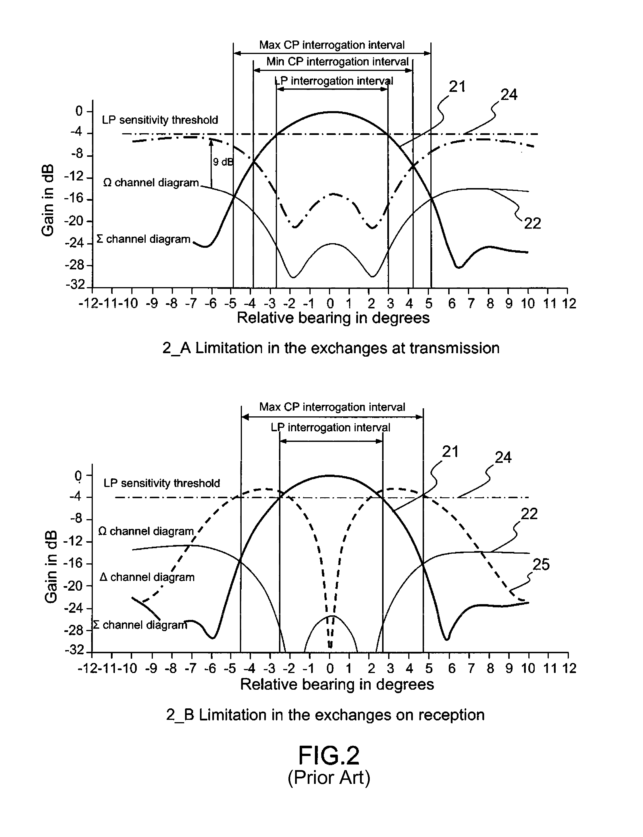
Consequently, the effective interrogation arc of the radar (1030 MHz), which corresponds to the region of space within which the transponder is capable of responding, is therefore limited:
the Losses mentioned being mainly due to the losses resulting from the propagation of the signals between the radar and the aircraft.
Thus, in particular for operation in S mode or in IFF mode, the operational mode of the various channels of the secondary surveillance radar described previously, as regards the exchanges of information between the radar and the various transponders, leads to limitations in the use of the signals in transmission and in reception.
Currently, these operational limitations are turning out to be increasingly incompatible with the operational limitations supported by the secondary surveillance radar systems responsible for the control of the air traffic, such as for military radar systems responsible for the IFF identification.
These growing limitations lead to constraints that are less and less compatible with the current operation of secondary surveillance radar systems.

Method used


Image

  • Method for increasing the time for illumination of targets by a secondary surveillance radar
  • Method for increasing the time for illumination of targets by a secondary surveillance radar
  • Method for increasing the time for illumination of targets by a secondary surveillance radar

Examples


Embodiment Construction

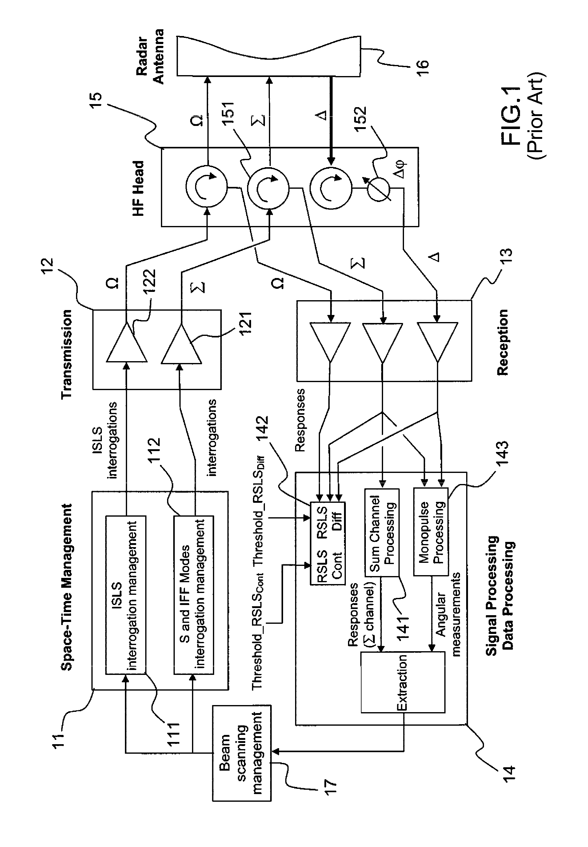
[0055]As is shown by the diagram in FIG. 1, the architecture of a current secondary surveillance radar operating in S and / or IFF modes may be broken down into various functional blocks amongst which may be identified:

[0056]The Space-Time Management 11 (STM), which notably manages the transmission of the SSR interrogation messages in S Mode or in IFF mode by taking into account the radar tasks to be performed relating to the targets whose presence in the antenna beam (main lobe) is predicted by taking into account past events;

[0057]The Transmitter 12 (TX), which converts the interrogation messages into high-power RF signals at a frequency F1 (1030 MHz), and transmits these signals for their radiation by the antenna;

[0058]The Receiver 13 (RX), which demodulates the RF signals received by the antenna at a frequency F2 close to F1 (1090 MHz);

[0059]The processor for processing the signal 14 (SP) which processes the signals coming from the receiver and which detects and decodes the respon...


PUM


Abstract

A secondary surveillance radar with rotating antenna, configured for transmitting interrogations in S or IFF mode and processing the responses to these interrogations. The radar includes an antenna having a lobe with three channels, a Sum channel, a Difference channel and a Control channel, whose transmission means are configured for transmitting interrogation messages over the Sum and Difference channels and whose reception and processing means are configured so as to carry out, aside from conventional detections by the Sum channel, detections by the Difference channel of the responses from the aircraft having been subjected to interrogation by this same channel. The radar also includes means for Space-Time Management configured for generating interrogation messages and determining whether a given message is to be transmitted by the Sum channel, by the Difference channel or by the two channels simultaneously and controlling its transmission by the corresponding transmission channel.

Description

CROSS-REFERENCE TO RELATED APPLICATION[0001]This application claims priority to foreign French patent application No. FR 1003751, filed on Sep. 21, 2010, the disclosure of which is incorporated by reference in its entirety.FIELD OF THE INVENTION[0002]The invention relates to the general field of secondary surveillance radar systems. It relates, more particularly, to the process of interrogation of aircraft by a secondary surveillance radar of the monopulse type, in particular for interrogations in S mode or in IFF mode.BACKGROUND[0003]The antennas that equip current secondary surveillance radar (SSR) systems are generally large antennas (4 to 9 m wide) which conventionally possess 3 transmission / reception channels: a channel referred to as “Sum channel” or “Σ channel”, a channel referred to as “Difference channel” or “Diff channel” or else “Δ channel”, and a complementary channel referred to as “Control channel” or “Cont channel” or else “Ω channel”. By virtue of their design, these...

Claims


Application Information

Patent Timeline
Patent Type & Authority Patents(United States)
IPC IPC(8): G01S13/78G01S13/44
CPCG01S7/034G01S13/44G01S7/282G01S13/782
Inventor BILLAUD, PHILIPPE, JEAN, PATRICK
Owner THALES SA
Learn More