Each of these systems has a variety of drawbacks, typically related to
system cost and complexity.
The largest components of the
system costs are the initial installation costs and the cost of each AGV.
Issues related to the complexity of the system typically include limited guide path revision flexibility, high costs associated with any guide path revisions, complex and heavy processor use during operation, and for some systems, limited operational accuracy.
However, the initial installation costs of these electrified guide wire systems within the facility in which the AGVs operate are extremely high in comparison to other guidance systems and an electrified guide wire system has extremely limited guide path revision flexibility and high costs associated with any such revisions to the guide paths.
More specifically, any change in a
route the AGV follows requires tearing up the floor of the facility, removing existing electrified guide path wires and replacing them with rerouted guide path wires, all resulting in significant inconvenience or down time for the facility.
Optical guidance systems have made significant strides in improved accuracy, but typically require expensive sensors and controllers with substantial
processing power to process the graphical images used in guidance of the AGV, which increases the cost and complexity of each AGV.
Inertial guidance systems, similar to optical guidance systems, have significantly improved their capabilities, however, inertial guidance systems using encoders and gyroscopes also typically require significant
processing power.
As such, the guidance systems for these AGVs are generally expensive and complex in comparison to the guidance systems for AGVs that follow an electrified guide wire.
While optical and inertial guidance systems do not require tearing up the floor of a facility to make route changes, similar to most guidance systems, any route changes may require substantial time and costs for the system to learn the new route.
In optical and inertial guidance systems, at least one AGV typically must be taught the new route and in some systems, a new map of the facility must be created, which can be
time consuming and require specialized expertise.
As such, the components on the AGV relating to the
guidance system may have substantially greater costs and complexity than similar components on any AGV in an electrified guide wire system.
Due to the weaker
magnetic field generated by these passive magnetic materials, some AGVs have experienced issues in accurately and precisely tracking the guide paths formed by the passive magnetic materials.
While the installation costs are much lower and route revisions are much cheaper than electrified guide wire systems, the weaker magnetic fields of these passive magnetic materials may limit the ability of traditional magnetic sensors on the AGV, previously used with electrified
guide wires, to determine the precise location of the weaker
magnetic signal, especially in facilities having strong background or ambient magnetic fields.
One problem with discrete magnetic markers is that the AGV must be presumed to be in alignment with the path defined by the discrete
magnet markers.
During operation, if errors compound, such as a heading error increasing to a point where correction is not possible, the sensors on the AGV may be too far displaced from the next marker to obtain a valid reading of the next marker.
Missing or displaced magnetic markers are also problematic, as once the AGV is misaligned with the actual path, most current methods of using discrete markers are unable to correct the AGV's path sufficiently to detect the next correctly located discrete marker in the pathway.
More specifically, even when the AGV is traveling along a straight pathway, if the next expected
magnetic marker is displaced to one side from its proper position, the AGV may initiate a turn based on the location of the displaced marker, which may cause the heading of the AGV to be too far deviated from the correct pathway to locate the subsequent properly placed marker.
These issues are particularly acute in areas where an AGV must make a turn.
These encoding systems are typically limited to a small amount of information and may even require many individual magnets to form a single marker to
encode enough information.
The requirements for these individual, specialized magnets increases the cost of installation and overall complexity of the system, while the practicality of the system is limited in view of the limited amount of information capable of being encoded.
While some systems have attempted to replace the discrete magnetic markers in turns with a continuous marker, such as a magnetic bar, these bars are typically expensive to install, may require facility renovations and may require expensive custom
radius magnetic bars in the turns.
However, due to the typically weaker magnetic fields emitted by these continuous markers, as compared to electrified
guide wires and even discrete magnetic markers, the magnetic sensors used on these AGVs have increased in cost and the
processing power required for tracking has also increased to ensure accurate and precise tracking similar to the tracking obtained in electrified guide wire systems with a stronger magnetic field.
The cost of these systems is increased due to the number of sensors used, and the amount of processing power required to process the twelve different signals.
The AGV's cost is also increased in that typically at least two sensors are also used to detect stray, ambient, or background magnetic fields.
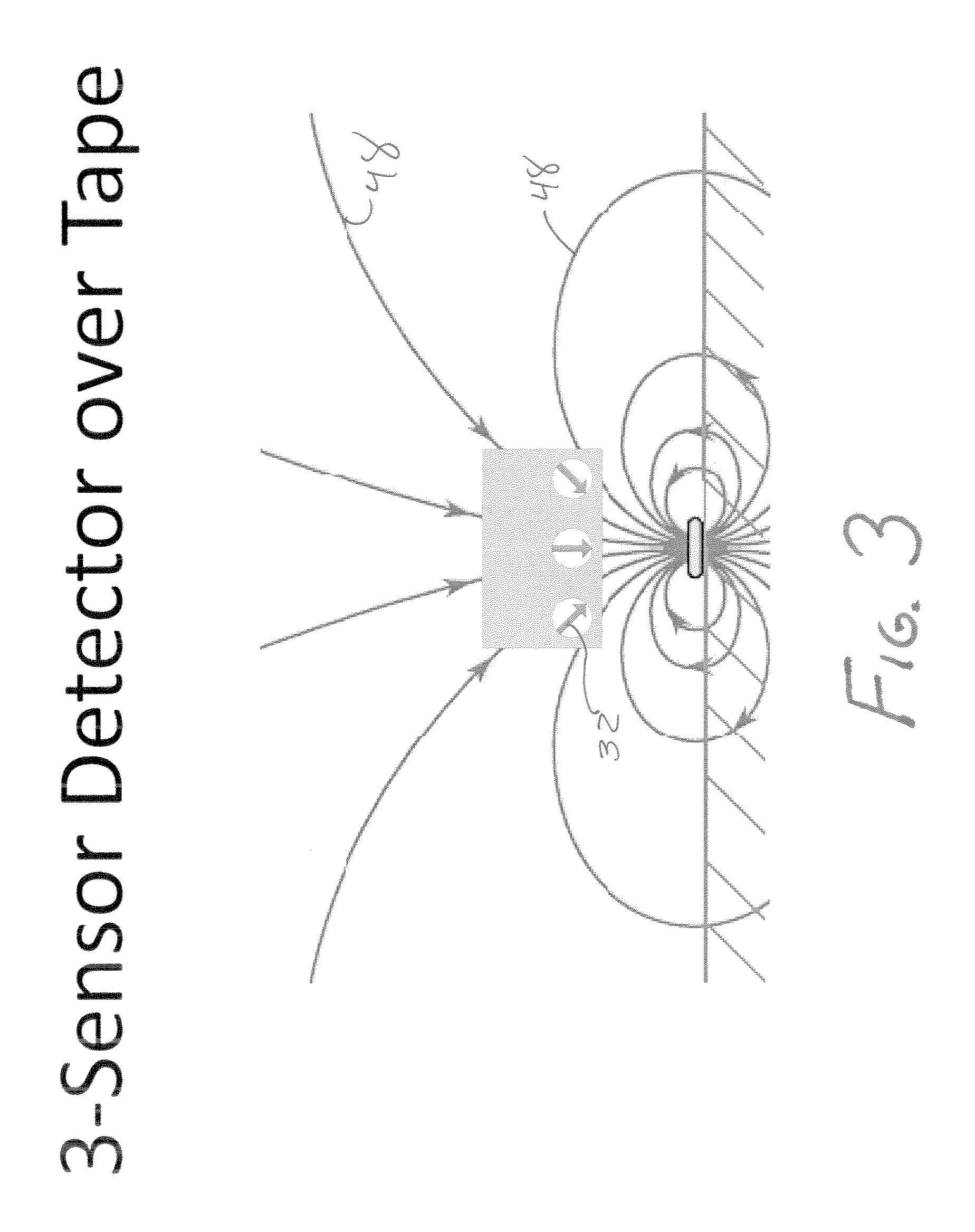
The effectiveness of these background magnetic sensors is limited since these sensors only detect one component of the three components in the magnetic field.
Another problem with current magnetic sensor assemblies following a passive and continuous magnetic marker is that the algebraic relationship used to calculate the location of the AGV is not only sensitive to the width of the marker, but also the height of the sensor from the magnetic marker.
As such, minor deviations in the width of the marker or height of the sensor on the AGV may cause variations in locating a magnetic marker.
As the height of the sensor from the magnetic marker is required in calculating the position of the magnetic marker, it is very important that the height of the sensor
assembly during the
assembly of the AGV precisely matches the specified height, raising costs of
assembly or requiring specific calibration of each AGV in relation to height.
The requirement for the height to be precisely known is also problematic as it may vary depending on the amount of load the AGV is carrying or due to the variations in the floor of the facility.
Additionally, the requirement for the width of the magnetic marker to be consistent over its entire length is problematic.


