Method for displaying information in a motor vehicle and display device for a motor vehicle

a technology for displaying information and motor vehicles, which is applied in the direction of control devices, vehicle components, instruments, etc., can solve the problems of inability to safely drive the motor vehicle, safety risks, and undesirable user operation drawbacks, and achieve intuitive and simple operator control of the vehicle device. , the effect of easy operation

Active Publication Date: 2014-03-18
VOLKSWAGEN AG
View PDF67 Cites 0 Cited by
  • Summary
  • Abstract
  • Description
  • Claims
  • Application Information

AI Technical Summary

Benefits of technology

[0008]Example embodiments of the present invention provide a method and a display device of the type indicated at the outset, in which the displayed information is able to be comprehended as quickly and intuitively as possible, and which permit a rapid, intuitive and simple operator control of vehicle devices whose information is displayed.
[0011]Usually, the information display in a motor vehicle has both display contents together in various areas of the display. According to example embodiments of the present invention, the display contents which include the pure rendering of information that is not connected to operating steps are shown in a display field of a graphical object, and separately from that, the display contents which include the visual display of operating steps are shown in an operating field. This separation of the information contents makes it easier for the viewer to quickly and intuitively take in the displayed information, so that safety in driving the vehicle is thereby increased since the driver is distracted to a lesser extent from the driving of the vehicle by the absorption of the displayed information.
[0012]According to example embodiments of the present invention, the separation of the display field and the operating field of the graphical object is further visualized for the viewer in that the two fields are represented on different sides of a two-dimensional graphical object, and with the aid of an input, the viewer is able to rotate the perspective representation of the graphical object on the display from one side to the other side, and thus is able to get from the display field to the operating field and vice versa.
[0021]According to example embodiments of the present invention, the speed of the motor vehicle is measured, and the duration of the total rotation or the duration of the rotation of the first and / or second phase is ascertained as a function of the speed of the motor vehicle. By preference, the higher the speed of the motor vehicle, the longer the duration of the rotation. Namely, at higher speeds, the driver can only direct his eye toward the display for shorter time intervals. Moreover, the spacing of the time intervals in which the driver directs his eye toward the display is greater, since at higher speeds, the driver must focus greater attention on the driving process. The coupling of the rotational duration of the two-dimensional object to the speed of the motor vehicle therefore ensures that at higher speeds, the driver retains his orientation in the information display, and in this manner, is able to comprehend the information contents easily, quickly and intuitively.

Problems solved by technology

If such menu structures are used in a motor vehicle, the problem arises that navigation within these menu structures and the absorption of the information indicated by the display claim the attention of the driver in such a way that he is no longer able to safely drive the motor vehicle at the same time.
However, such drawbacks for the user operation are undesirable.
In many cases, the result is that the driver operates the devices in the vehicle while driving, although this leads to a distraction which can represent a safety risk.
In this context, many animation techniques which are used outside of the motor vehicle for the variable graphical display of objects are unsuitable for use in the motor vehicle, since in the motor vehicle, the viewer only looks at the display for brief moments.

Method used


Image

  • Method for displaying information in a motor vehicle and display device for a motor vehicle
  • Method for displaying information in a motor vehicle and display device for a motor vehicle
  • Method for displaying information in a motor vehicle and display device for a motor vehicle

Examples


Embodiment Construction

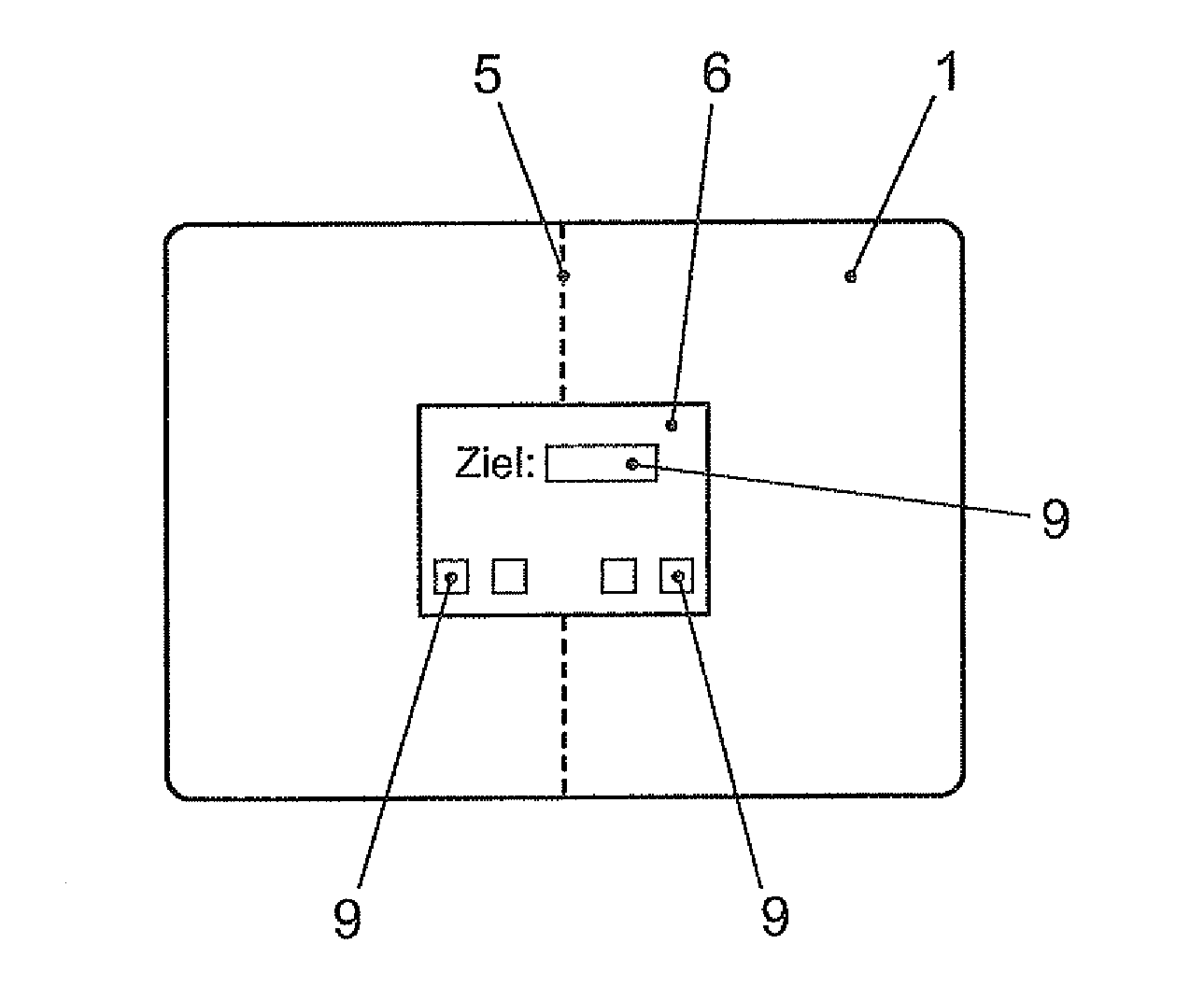
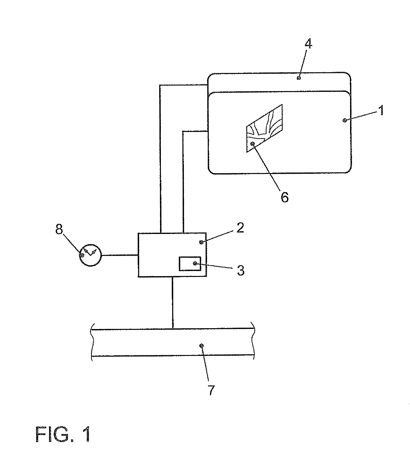
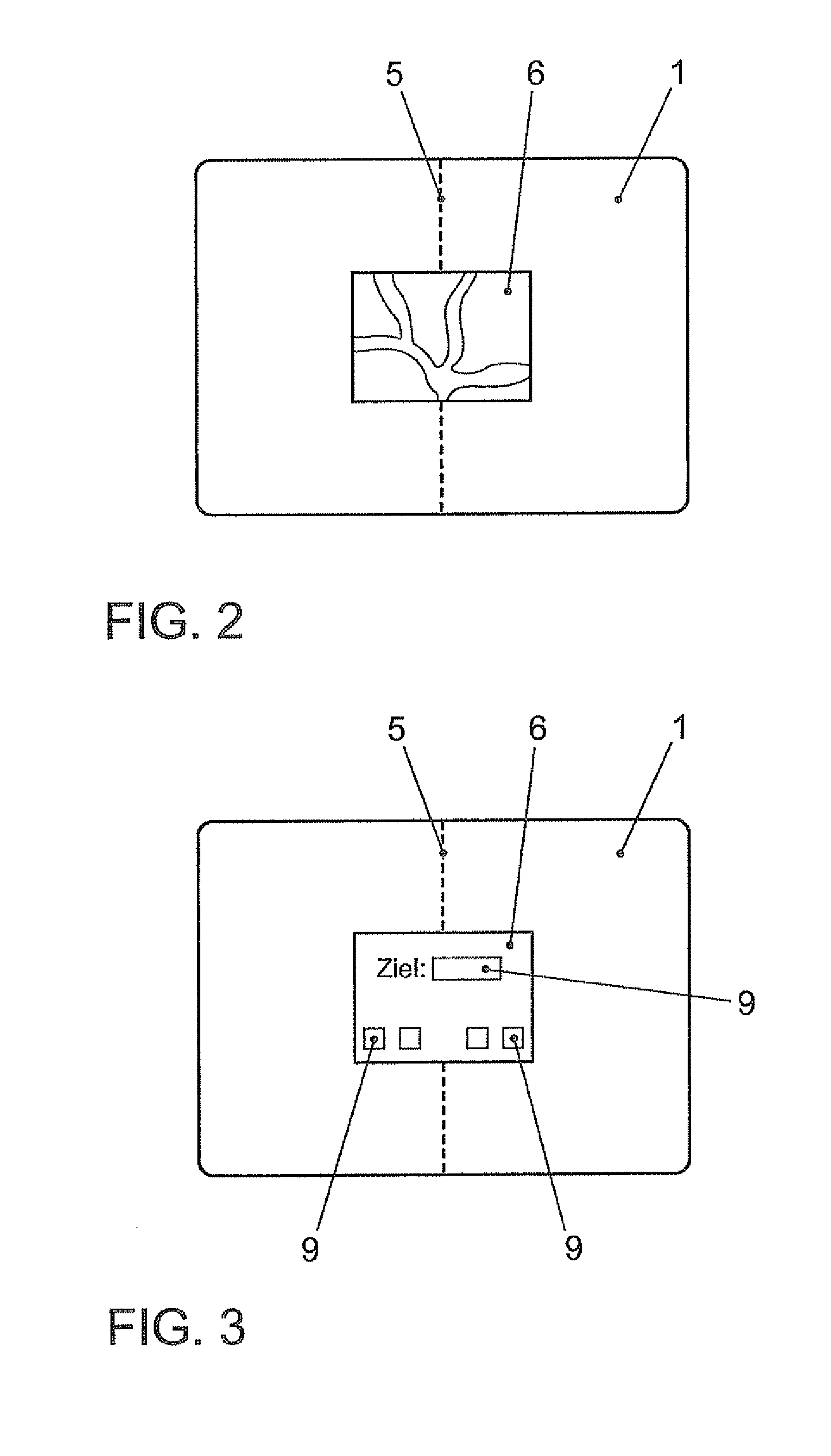
[0037]The display device includes a display 1 for the graphical representation of information. Display 1 may be a matrix display, e.g., an LCD (liquid crystal display), especially a color display using TFT (thin-film transistor) technology. Furthermore, the display may be what is referred to as a twisted nematic-liquid crystal display (TN-LCD), a super twisted nematic (STN) display, a double-layer STN, an FLC (ferroelectric liquid crystal) display or an SSFLC (surface stabilized ferroelectric liquid crystal). Assigned to display 7 is a back-lighting (not shown) which may be provided by one or more light-emitting diodes. Display 1 is freely programmable, that is, any desired graphics data may be generated, which are represented on display 1.

[0038]In particular, display 1 is mounted in an area of the vehicle that is clearly visible for at least the driver. If the operator control of the devices of the vehicle is directly coupled to the placement of the display, so that, for example, t...


PUM


Abstract

In a method for displaying information in a motor vehicle, at least one two-dimensional object is represented graphically with the aid of a display mounted in the motor vehicle, the graphical object including a display field and an operating field. A user-interface device generates graphics data which control the display such that the display field is shown on one side of the two-dimensional graphical object and the operating field is shown on the other side of the two-dimensional graphical object, and in response to an input with the aid of an input device, an arithmetic logic unit of the user-interface device alters the graphics data such that the object in the perspective representation on the display rotates from one side to the other side. A corresponding display device is provided for a motor vehicle, and a motor vehicle may include such a display device.

Description

FIELD OF THE INVENTION[0001]The present invention relates to a method for displaying information in a motor vehicle, in which at least one two-dimensional object is represented graphically with the aid of a display mounted in the motor vehicle, the graphical object including a display field and an operating field. The present invention further relates to a display device for a motor vehicle having a display for the graphical representation of information, a user-interface device by which at least one graphical object displayable on the display is able to be generated, the graphical object including a display field and an operating field, and an input device coupled to the user-interface device.BACKGROUND INFORMATION[0002]In a motor vehicle, there are various information and communication areas to which indicating instruments are assigned. They are used to provide information to the driver and passengers. Moreover, they are able to assist the driver in navigation or communication wit...

Claims


Application Information

Patent Timeline
Patent Type & Authority Patents(United States)
IPC IPC(8): G06F3/14G06F13/00
CPCB60K35/00B60K2350/1004B60K37/06B60K2350/2017B60K2370/11B60K2370/1531
Inventor DEHMANN, RAINERKUHN, MATHIAS
Owner VOLKSWAGEN AG
Why Eureka
Try Eureka