
Method for displaying information in a vehicle and display device for a vehicle

a technology for displaying information and vehicles, applied in control devices, vehicle components, instruments, etc., can solve problems such as safety risks, undesirable drawbacks for user operation, and no longer being able to safely drive motor vehicles, and achieve intuitive and simple operator control of vehicle devices

Active Publication Date: 2011-08-25
VOLKSWAGEN AG
View PDF20 Cites 45 Cited by
  • Summary
  • Abstract
  • Description
  • Claims
  • Application Information

AI Technical Summary

Benefits of technology

[0008]In a method and a display device of the type indicated at the outset, the displayed information is able to be comprehended as quickly and intuitively as possible, and a rapid, intuitive and simple operator control of vehicle devices whose information is displayed is provided.
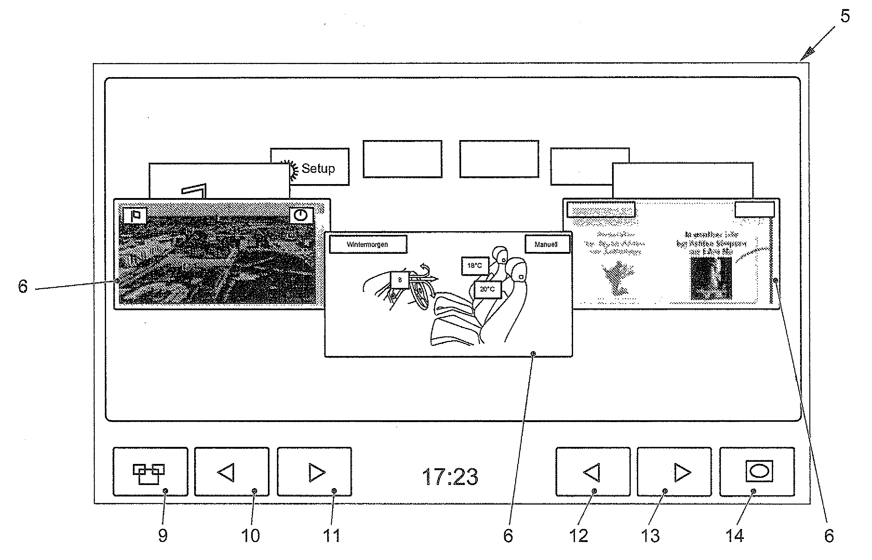
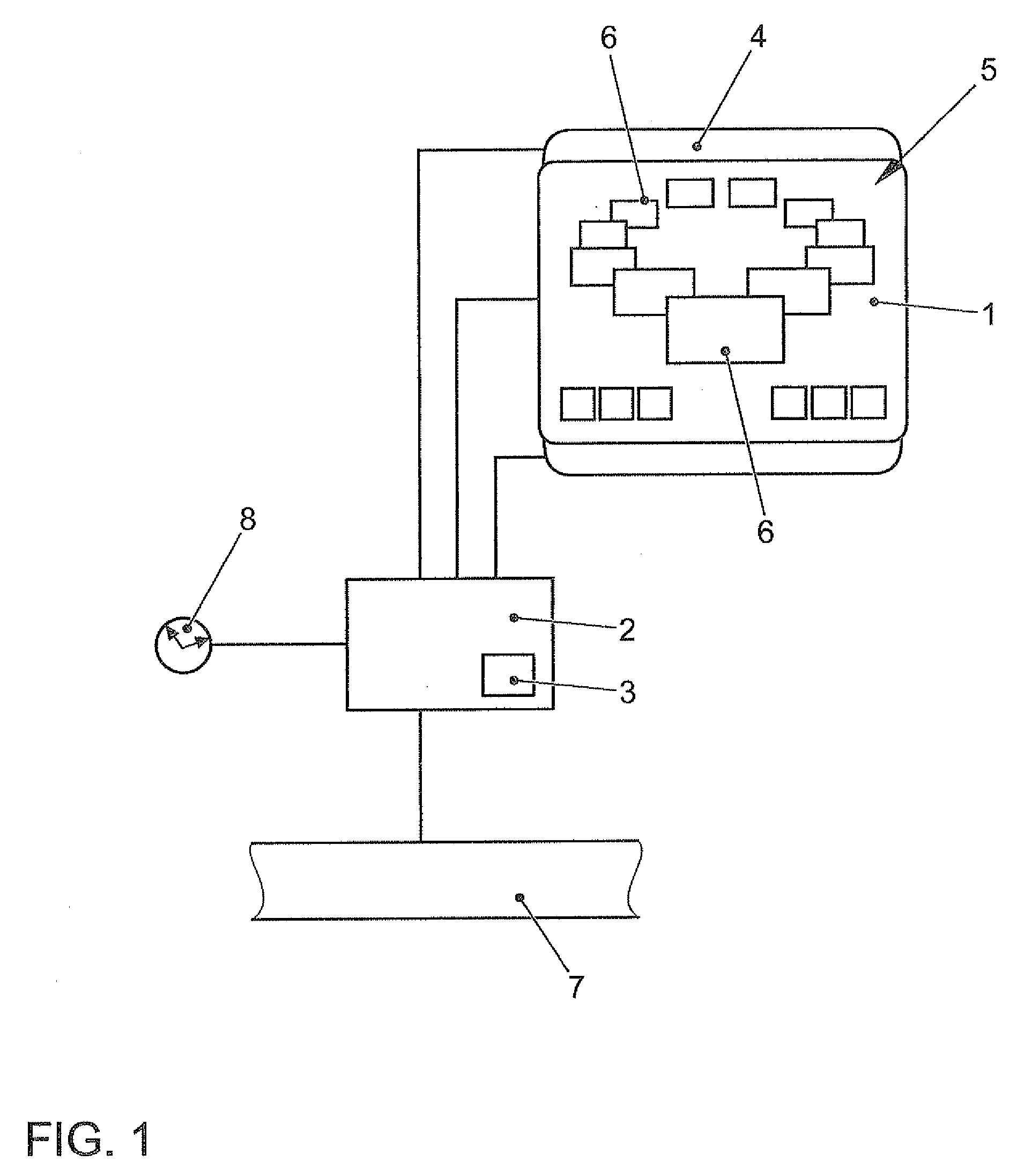
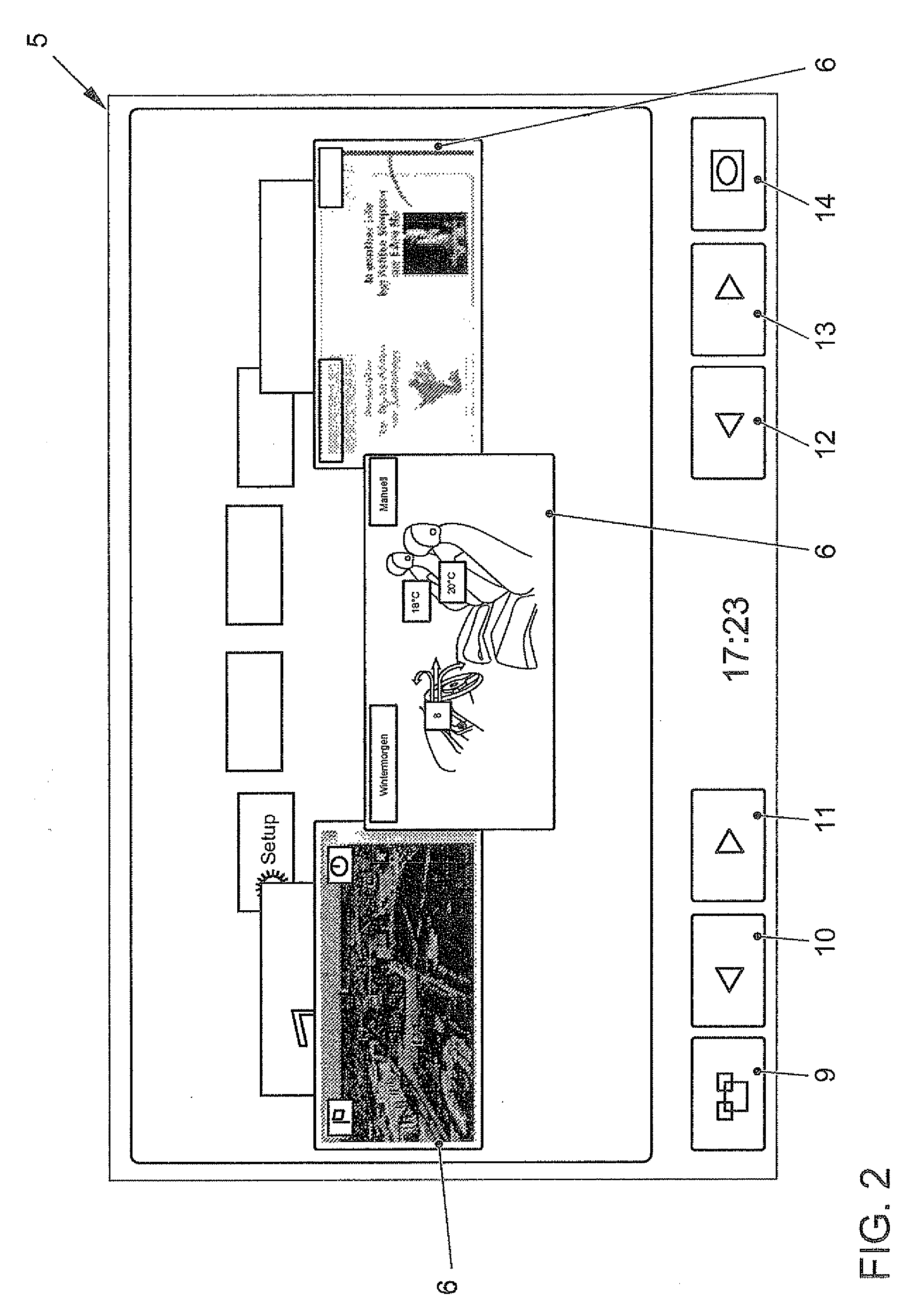
[0011]The depiction of the objects on a virtual ring has the advantage that, even if a multitude of objects are displayed graphically, the viewer finds his way very easily and quickly, and therefore the safety of the vehicle is not impaired, even if the driver absorbs the information displayed by the display while he is driving and, if necessary, operates the vehicle devices assigned to the objects.
[0026]The speed of the motor vehicle may be measured, and the duration of the total rotation may be ascertained as a function of the speed of the motor vehicle. By preference, the higher the speed of the motor vehicle, the longer the duration of the rotation. Namely, at higher speeds, the driver can only direct his eye toward the display for shorter periods. Moreover, the spacing of the time intervals in which the driver directs his eye toward the display is greater, since at higher speeds, the driver must focus greater attention on the driving process. The coupling of the rotational duration of the two-dimensional object to the speed of the motor vehicle therefore ensures that at higher speeds, the driver retains his orientation in the information display, and in this manner, is able to comprehend the information contents easily, quickly and intuitively.
[0028]Furthermore, in a display state in which only the activated object is displayed, as a result of an input for the carousel-like rotation of the objects, the last activated object merges into the carousel-like display within the further objects, the objects on the virtual ring rotate in carousel fashion by one position, the virtual ring is again hidden, and finally only the next object is displayed. Because of this change of display in the rendering of the objects, the viewer is able to orient himself more easily within the structure of the displayed objects, even if in each instance he looks at the changing display for only brief time periods, as is often the case in a motor vehicle when the driver absorbs the presentation of information.
[0029]After a carousel-like shift of the objects on the virtual ring, the object displayed in the foreground may be activated automatically after a time interval has elapsed. The user therefore only has to rotate the object to be activated into the foreground. The further operating step of activation may be omitted, so that after the object has been rotated, the user may turn his eye away from the display and does not have to further manipulate the input device. This is particularly advantageous for use in a motor vehicle, since the distraction of a driver who is looking at the display and operating the input device is reduced to a minimum.

Problems solved by technology

If such menu structures are used in a motor vehicle, the problem arises that navigation within these menu structures and the absorption of the information indicated by the display claim the attention of the driver in such a way that he is no longer able to safely drive the motor vehicle at the same time.
However, such drawbacks for the user operation are undesirable.
In many cases, the result is that the driver operates the devices in the vehicle while driving, although this leads to a distraction which can represent a safety risk.
In this context, many animation techniques which are used outside of the motor vehicle for the variable graphic display of objects are unsuitable for use in the motor vehicle, since in the motor vehicle, the observer only looks at the display for brief moments.

Method used


Image

  • Method for displaying information in a vehicle and display device for a vehicle
  • Method for displaying information in a vehicle and display device for a vehicle
  • Method for displaying information in a vehicle and display device for a vehicle

Examples


Embodiment Construction

[0046]The display device includes a display 1 for the graphical representation of information. Display 1 may be a matrix display, e.g., an LCD (liquid crystal display), especially a color display using TFT (thin-film transistor) technology. Furthermore, the display may be what is referred to as a twisted nematic-liquid crystal display (TN-LCD), a super twisted nematic (STN) display, a double-layer STN, an FLC (ferroelectric liquid crystal) display or an SSFLC (surface stabilized ferroelectric liquid crystal). Assigned to display 7 is a back-lighting (not shown) which may be provided by one or more light-emitting diodes. Display 1 is freely programmable, that is, any desired graphics data may be generated, which are represented on display 1.

[0047]In particular, display 1 is mounted in an area of the vehicle that is clearly visible for at least the driver. If the operator control of the devices of the vehicle is directly coupled to the placement of the display, so that, for example, t...


PUM


Abstract

In a method for displaying information in a motor vehicle, a plurality of objects are represented graphically with the aid of a display mounted in a motor vehicle. A user-interface device generates graphics data which control the display such that the graphical objects are shown disposed on a virtual, perspectively displayed ring, and that in response to an input with the aid of an input device, an arithmetic logic unit of the user-interface device alters the graphics data such that the graphical objects on the virtual ring rotate like a carousel. A corresponding display device is provided.

Description

FIELD OF THE INVENTION[0001]The present invention relates to a method for displaying information in a motor vehicle, in which a plurality of objects are represented graphically with the aid of a display mounted in the motor vehicle. The present invention further relates to a display device for a motor vehicle having a display for the graphic representation of information which is mounted in the motor vehicle, a user-interface device by which graphics data are able to be generated for objects displayable on the display, and an input device coupled to the user-interface device.BACKGROUND INFORMATION[0002]In a motor vehicle, there are various information and communication areas to which indicating instruments are assigned. They are used to provide information to the driver and passengers. Moreover, they are able to assist the driver in navigation or communication with the outside world. In particular, the display is able to visually represent vehicle data related to traffic or operatio...

Claims


Application Information

Patent Timeline
Patent Type & Authority Applications(United States)
IPC IPC(8): G06F3/041G09G5/00G06F3/048G06F3/0482G06F3/0488
CPCB60K35/00B60K2350/1004G06F3/04883G06F3/0482B60K2350/2017B60K35/10B60K2360/11B60K35/211
Inventor WALLER, CHRISTOPHLEMKE, KATJADEHMANN, RAINERKUHN, MATHIAS
Owner VOLKSWAGEN AG
Learn More