Carrier tape feeder

a feeder and carrier tape technology, applied in the direction of instruments, packaged goods types, instruments, etc., can solve the problems of deterioration of workability, continuous feeding of carrier tapes, prolonged working time, etc., and achieve the effect of simplifying the discharge process of carrier tapes and improving productivity

Active Publication Date: 2014-03-25
STS +1
View PDF5 Cites 15 Cited by
  • Summary
  • Abstract
  • Description
  • Claims
  • Application Information

AI Technical Summary

Benefits of technology

[0008]It is, therefore, an object of the present invention to provide a carrier tape feeder that folds cover tapes separated from base tapes in the lengthwise direction and discharges the cover tapes and the base tapes simultaneously, which simplify the discharge process of the carrier tapes and prevent the cover tapes from getting entangled or coming into contact with each other to generate static electricity, leading to productivity improvement, and that enables continuous loading of a plurality of carrier tape reels.

Problems solved by technology

Such loading process makes it impossible to continuously feed carrier tapes into the carrier tape feeder, causing prolonged working time.
Further, an operator must watch the feeding state of the carrier tapes to check whether the carrier tapes are exhausted, which becomes a cause of deterioration in workability.
However, this design may cause entangling of the cover tapes to generate static electricity.
Further, materials for the cover tapes may cause variations in the pitch of the carrier tapes in view of their characteristics, making it difficult to pick up electronic chips accurately.
This case may cause more serious static electricity problems because a larger number of cover tapes discharged from the tape feeders get entangled or come into contact with each other.
Such static electricity problems may increase the number of defects or may lead to an increase in working time, giving a negative influence on productivity.

Method used


Image

  • Carrier tape feeder
  • Carrier tape feeder
  • Carrier tape feeder

Examples


Embodiment Construction

[0038]Exemplary embodiments of the present invention will now be described in detail.

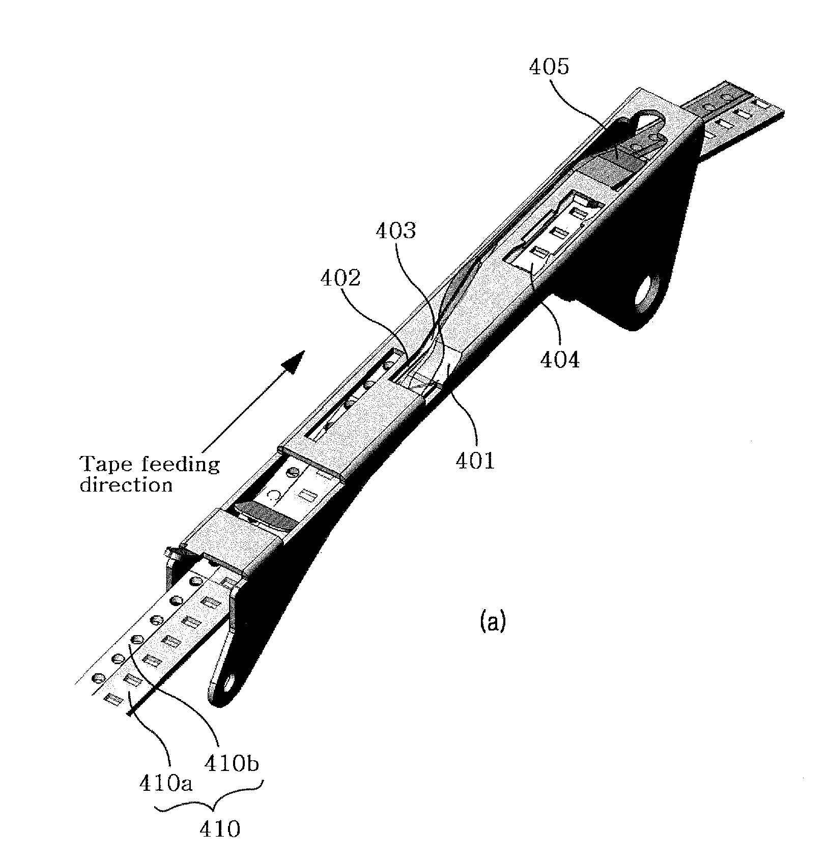
[0039]The present invention provides a carrier tape feeder including a unit for loading a carrier tape, a picking-up unit and a driving unit, wherein the pick-up unit includes a knife portion for separating a cover tape from a base tape in a first adhesive portion, a folding-guiding portion spaced from one lateral side of the knife portion to induce folding of the cover tape separated by the knife portion in the lengthwise direction in a state in which the cover tape is partially attached to the base tape in a second adhesive portion, and an inversion-guiding portion extending in an oblique direction from the knife portion and the folding-guiding portion toward the outside of the carrier tape to induce inversion of the upper and lower surfaces of the cover tape folded in the folding-guiding portion so as to be superimposed on the base tape, and wherein the distal end of the lateral side of the foldi...


PUM

PropertyMeasurementUnit
angleaaaaaaaaaa
angleaaaaaaaaaa
pressureaaaaaaaaaa

Abstract

A carrier tape feeder is provided. The carrier tape feeder includes a unit for loading a carrier tape, a picking-up unit where chips are picked up, and a driving unit. The pick-up unit includes a knife portion, a folding-guiding portion, and an inversion-guiding portion. The knife portion separates a cover tape from a base tape in a first adhesive portion. The folding-guiding portion is spaced from one lateral side of the knife portion to induce folding of the cover tape separated by the knife portion in the lengthwise direction in a state in which the cover tape is partially attached to the base tape in a second adhesive portion. The inversion-guiding portion extends in an oblique direction from the knife portion and the folding-guiding portion toward the outside of the carrier tape to induce inversion of the upper and lower surfaces of the cover tape folded in the folding-guiding portion so as to be superimposed on the base tape. The distal end of the lateral side of the folding-guiding portion opposed to the knife portion extends above the second adhesive portion.

Description

BACKGROUND OF THE INVENTION[0001]1. Field of the Invention[0002]The present invention relates to a carrier tape feeder, and more specifically to an apparatus for continuous feeding of carrier tapes into a chip mounter.[0003]2. Description of the Related Art[0004]A chip mounter is an apparatus for high-speed, high-precision mounting electronic chips fed from a feeder on preset positions of a printed circuit board. In such a chip mounter, suction nozzles of a head are used to mount electronic chips. With the recent trend toward multifunctional, high-specification and downsized electronic devices, the need is increasing to develop techniques for mounting electronic chips in high density on printed circuit boards of the electronic devices. Technology for mounting chips on printed circuit boards is shifting from through-hole mounting to surface mounted technology (SMT). Surface mounted technology is used to directly mount chips in high density on the surface of printed circuit boards. Su...

Claims


Application Information

Patent Timeline
Patent Type & Authority Patents(United States)
IPC IPC(8): B32B38/10
CPCH05K13/0084H05K13/0417Y10T225/22Y10T156/1978H05K13/0215H05K13/0419
Inventor HWANG, YOUNG SOOKIM, YONG SUNGPARK, SU HONGKIM, HEE JONG
Owner STS
Why Eureka
Try Eureka