Container filling device

a filling device and container technology, applied in the direction of charging manipulation, lighting and heating apparatus, furnaces, etc., can solve the problems that the drive without chains for food products has not really caught on in the marketplace, and the elongation of the chain during operation requires frequent readjustmen

Active Publication Date: 2014-03-25
HAMBA FILLTEC
View PDF14 Cites 23 Cited by
  • Summary
  • Abstract
  • Description
  • Claims
  • Application Information

AI Technical Summary

Benefits of technology

[0012]A significant advantage of the support element with the gear rack is providing feeding without slippage between the drive and the support element. For the significant acceleration- and deceleration forces the form locking between the drive- and the support element provides controlled acceleration and deceleration.
[0013]Another essential advantage is achieved on the drive side. Herein a relatively small motor with a sprocket engaging the gear rack of the support element can be used, optionally with a transmission connected there between. The motor and the gear rack provide quick reaction. Relative to a linear piston described in EP 1495997 A1 the feed member of the drive does not have to perform any movement relative to the drive arrangement for the instant configuration of the support element.
[0015]It is another advantage that the gear rack itself can be used as a stabilization- or stiffening element for a plate of the support element that is designated as a cell plate and provided with receivers for the container.
[0016]A particularly preferred embodiment provides that the support elements are run through the device on rollers, wherein the rollers contact running rails at the device. Rollers facilitate running the support element through the device with minimized friction.
[0019]Arranging the gear rack on a top side of the support element furthermore has the advantage that in case of rollers the running rails provided at the filling device, or the respective component on which the support element is pushed through the device, is also used as a support bearing for the drive. Consequently the gear rack is arranged between the drive and the contact element at the device for the support element so that the gear rack cannot slide under the drive even when high acceleration- and deceleration forces occur.

Problems solved by technology

One of the essential disadvantages is that a chain elongation during operation not only requires frequent readjustment but additionally requires separate positioning at each of the operating stations acting upon the containers.
Drives without chains for filling devices for food products have not really caught on in the marketplace, however, there are already a few functional systems that operate reliably.

Method used


Image

  • Container filling device
  • Container filling device
  • Container filling device

Examples


Embodiment Construction

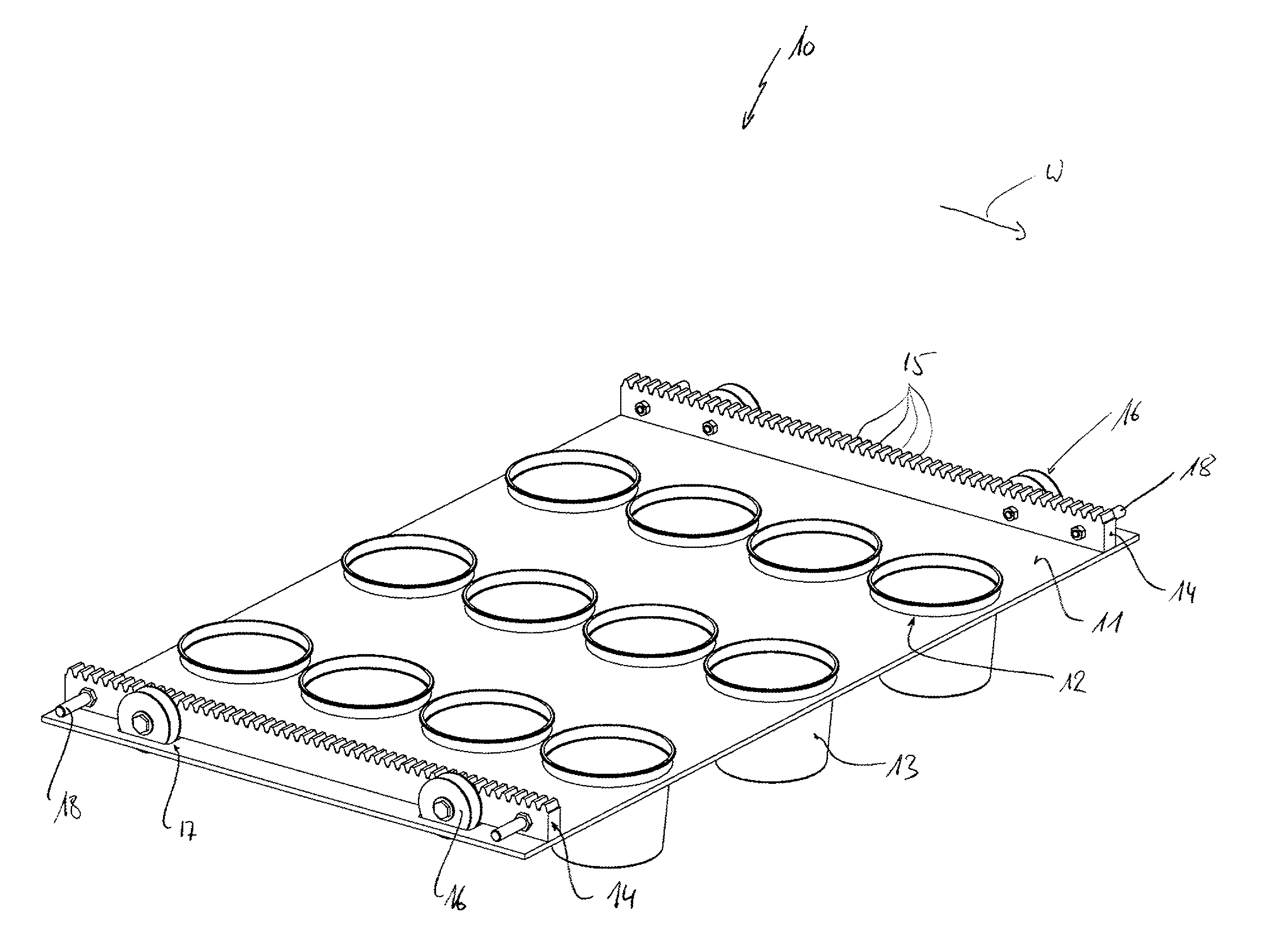
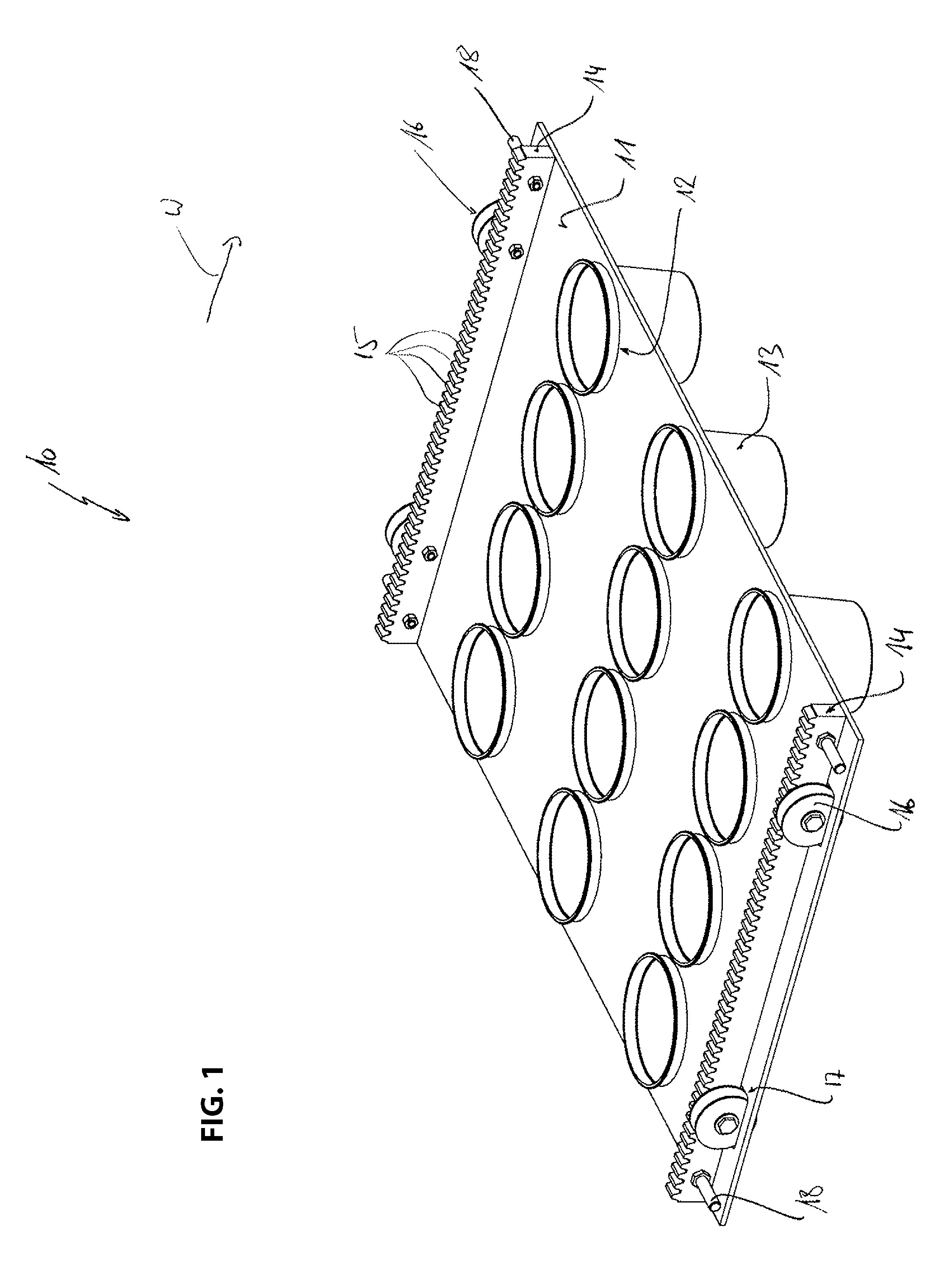
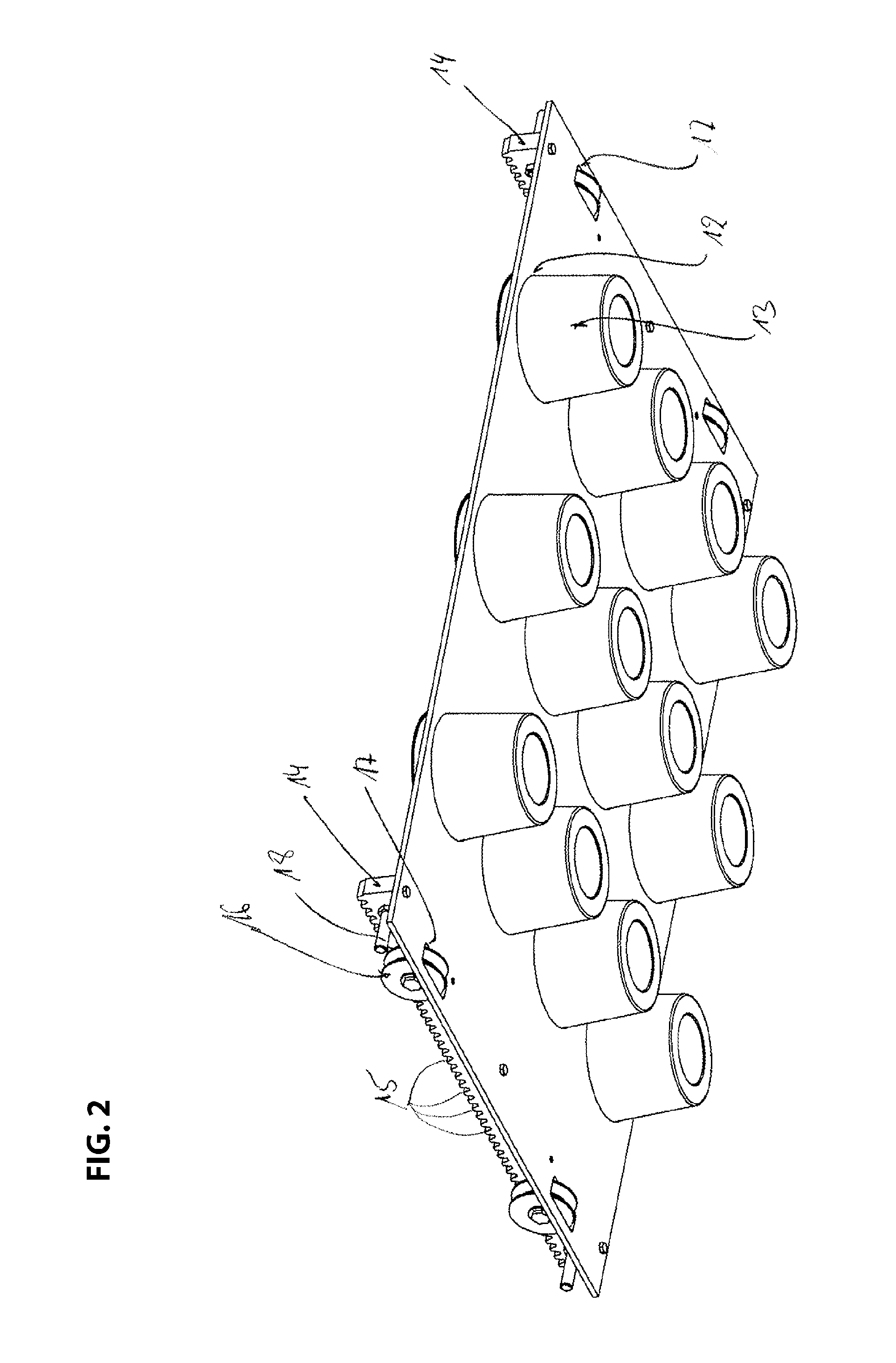
[0034]In the figures, the support element for the device according to the invention is designated overall with the reference numeral 10.

[0035]The support element 10 includes a so called cell plate 11. The cell plate 11 is typically a rectangular plate which is provided with plural receivers 12 for containers 13. The receivers are introduced into the cell plate in series transversal to a feed direction W and in tracks in the feed direction W.

[0036]FIG. 3 illustrates the filling device 1 with upper main element OT, lower main element UT, lateral elements ST and drive 19.

[0037]FIG. 4 illustrates a gear 23 of the drive 19 engaging a gear rack 14 of a support element 10 running on running rails 20.

[0038]On a top side of the support element 10 oriented towards operating stations gears racks 14 are arranged which extend in feed direction W. Each gear rack 14 includes a plurality of teeth 15 which are oriented away from the top side of the cell plate 11.

[0039]The gear racks 14 support rolle...


PUM


Abstract

A device for filling containers including an upper main element, a lower main element and lateral main elements connecting the upper and the lower main element; support elements arranged at one another without a continuous drive device, which support elements are provided with receivers for the containers and are run in an endless manner through the device past operating stations and along the main elements; a drive which runs the support elements in a feed direction at least through the upper main element or the lower main element along the operating stations; and operating elements arranged at the support elements through which a feed force of the drive is introduced into the support elements, wherein the operating elements at the support elements are gear racks in which a drive side feed member with a complementary teething engages in order to introduce the feed force into the support elements.

Description

RELATED APPLICATIONS[0001]This patent application claims priority from and incorporates by reference German patent application DE 10 2011 103 154.9 filed on May 25, 2011 and German patent application DE 10 2011 103 152.2 filed on May 25, 2011.FIELD OF THE INVENTION[0002]The present invention relates to a device for filling containers, in particular bottles or beakers, with food products, in particular liquid to paste-like dairy and fat products, juices, waters and similar, including an upper main element, a lower main element and lateral main elements connecting the upper element and the lower main element, a plurality of support elements arranged at one another without a continuous drive device, wherein the support elements are provided with receivers for the containers and are run in an endless manner through the device for filling the containers past operating stations and along the upper-, lower- and lateral main elements, including a drive which runs the support elements in fee...

Claims


Application Information

Patent Timeline
Patent Type & Authority Patents(United States)
IPC IPC(8): B65G29/00
CPCB65B43/54B65B43/52B65B65/02
Inventor JUNK, MARTIN
Owner HAMBA FILLTEC
Why Eureka
Try Eureka