Steering column device

a steering column and device technology, applied in the direction of steering parts, vehicle components, transportation and packaging, etc., can solve the problem of insufficient support stiffness and achieve the effect of fixing the steering column more stably

Active Publication Date: 2014-03-25
FUJI KIKO CO LTD
View PDF25 Cites 9 Cited by
  • Summary
  • Abstract
  • Description
  • Claims
  • Application Information

AI Technical Summary

Benefits of technology

[0010]An object of the present invention is to provide a steering column device which is capable of achieving stable fixation when performing a clamping operation of an operation lever.
[0021]According to this configuration, the clamp shaft is located in the center of the four contact portions. Hence it is possible to apply a clamping force from the clamp shaft substantially evenly to the respective contact portions and thereby to fix the steering column more stably.

Problems solved by technology

Accordingly, insufficient support stiffness may be obtained when the contact between the fixed longitudinal wall portion and the movable longitudinal wall portion is unstable.

Method used


Image

  • Steering column device
  • Steering column device
  • Steering column device

Examples


first embodiment

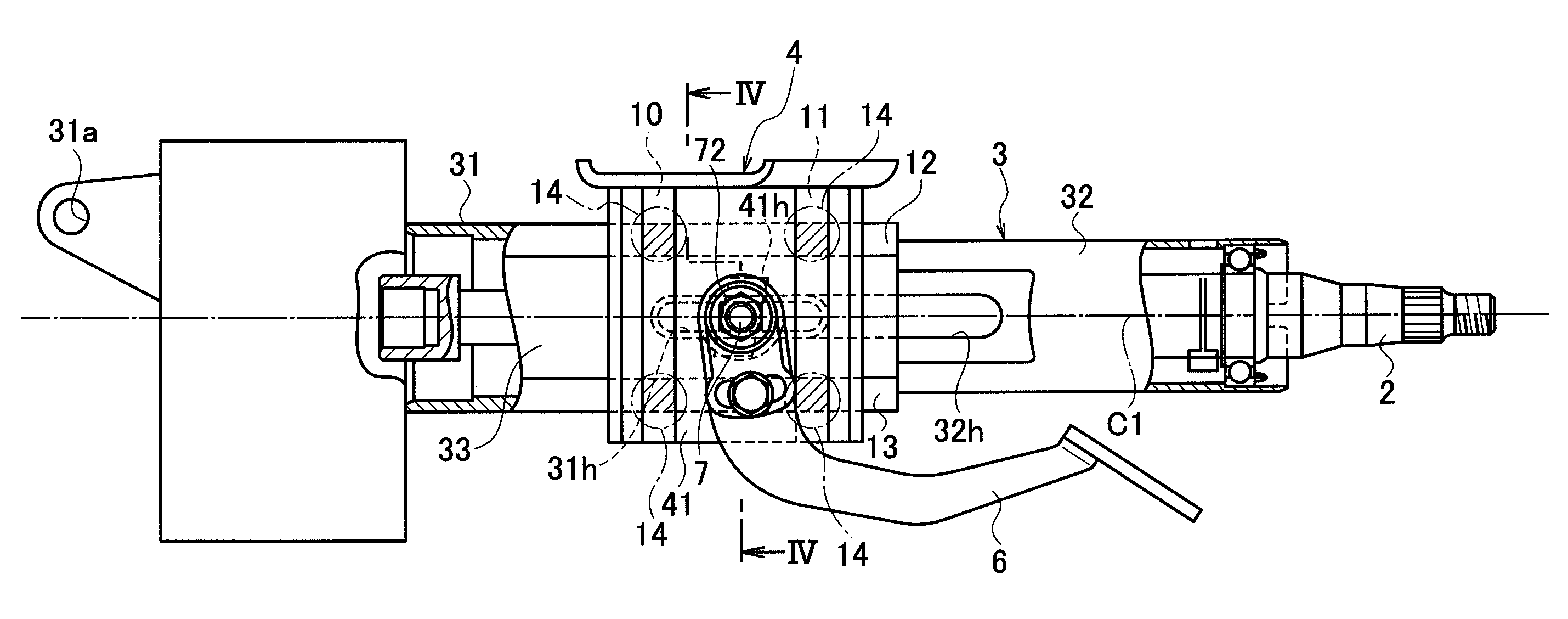
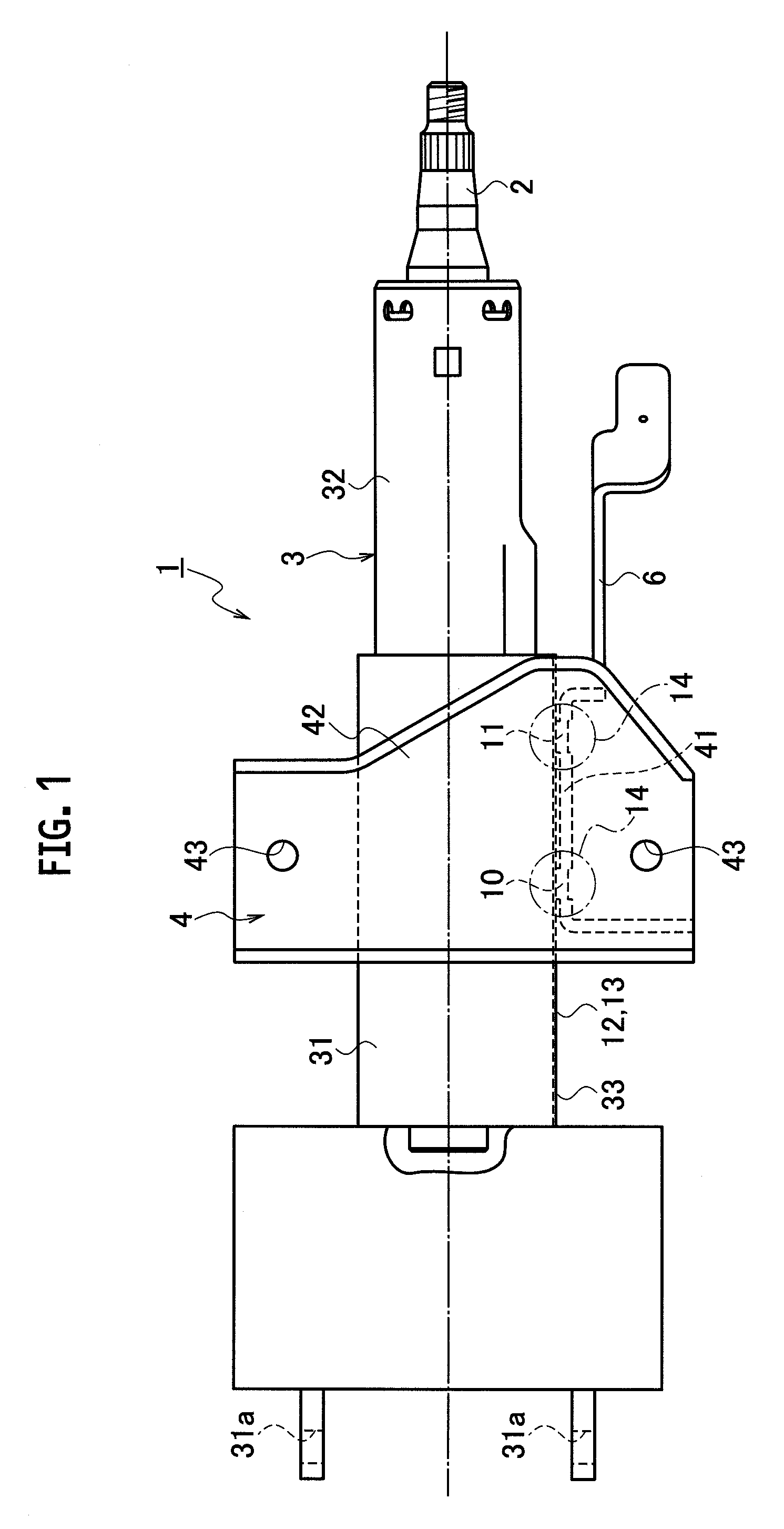
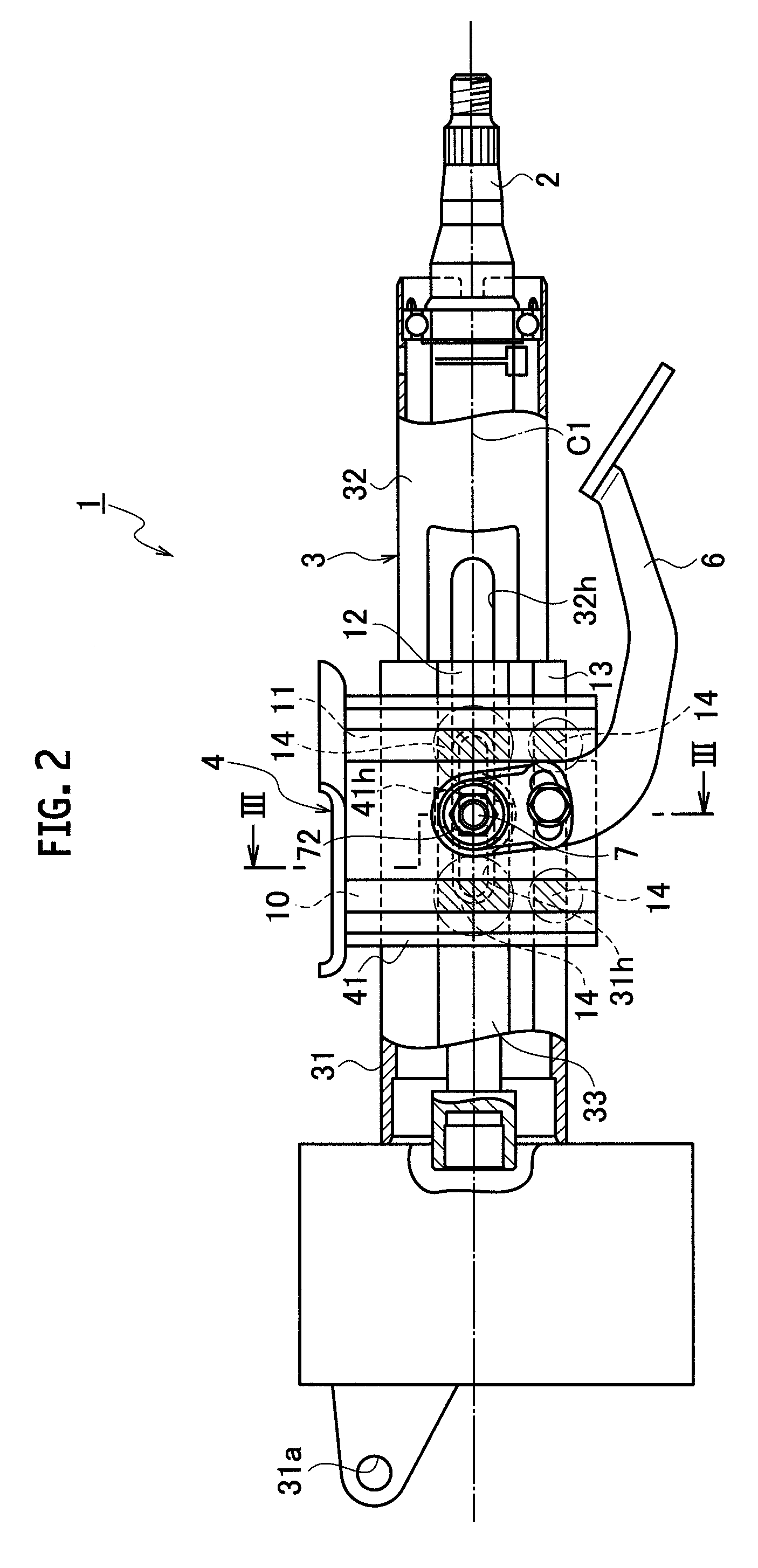
[0035]As shown in FIG. 1 to FIG. 3, a steering column device 1 of a first embodiment is configured to support a steering column 3 on a vehicle body side. Here, the steering column 3 houses a steering shaft 2 capable of performing a tilt operation and a telescopic operation of an unillustrated steering wheel. The steering column 3 includes a lower jacket 31 and an upper jacket 32 which are engaged with each other so as to be mutually movable in an axial direction. Overlapping portions of both of these jackets 31 and 32 are supported on the vehicle body side by a vehicle-body-side bracket 4.

[0036]The steering column device 1 generally includes the vehicle-body-side bracket 4, the steering column 3 (the lower jacket 31 and the upper jacket 32), and a clamp bolt 7, and is a cantilever type in which a fixed longitudinal wall portion (a first wall portion) 41 and a movable longitudinal wall portion (a second wall portion) 33 are provided on one side of the steering column 3.

[0037]The vehi...

second embodiment

[0049]FIG. 4 to FIG. 6 show a steering column device 1A according to a second embodiment of the present invention. In the drawings, the same constituents as those in the first embodiment are designated with the same reference numerals and duplicate description will be omitted herein.

[0050]As shown in FIG. 4 to FIG. 6, a key difference of the steering column device 1A of this embodiment from the steering column device 1 of the first embodiment is that the position of formation of the anteroposterior protrusion 12 is shifted to an upper end of the movable longitudinal wall portion 33 located above the center line C1 passing through the center of the clamp bolt 7.

[0051]Specifically, in this embodiment, the paired vertical protrusions 10 and 11 being separately disposed in the axial direction (the direction of the telescopic operation) of the steering column 3 while interposing the clamp bolt 7 therebetween and extending in the direction of the tilt operation (the vertical direction in ...

third embodiment

[0054]FIG. 7 to FIG. 9 show a steering column device 1B according to a third embodiment of the present invention. In the drawings, the same constituents as those in the first embodiment are designated with the same reference numerals and duplicate description will be omitted herein.

[0055]As shown in FIG. 7 to FIG. 9, a key difference of the steering column device 1B of this embodiment from the steering column device 1 of the first embodiment is that fixed longitudinal wall portions 41A and 41B and movable longitudinal wall portions 33A and 33B are respectively provided on both of right and left sides of the steering column 3 so as to establish a both-end support type.

[0056]Specifically, in this embodiment, the vehicle-body-side bracket 4 is substantially formed by disposing the fixed longitudinal wall portions 41A and 41B respectively on both of the right and left sides of the steering column 3, and fixing the upper side plate 42 having an inverted U-shaped cross section to upper en...


PUM


Abstract

A steering column device includes: a bracket to be fixed to a vehicle body and including a first wall; a steering shaft; a steering column including one end supported by the vehicle body and an outer peripheral surface with a second wall, and configured to rotatably support the steering shaft; and a clamp shaft penetrating the first wall and configured to switch between a pressure and non-pressure contact states respectively where the first and second walls are and are not in pressure contact with each other. The first and second walls include: a pair of first protrusions disposed separately on both sides of the clamp shaft in a first direction parallel to an axial direction of the steering column, and extending in a second direction perpendicular to the axial direction of the steering column; and a pair of second protrusions disposed separately in the second direction and extending in the first direction. Each of the first protrusions contacts both of the second protrusions in the pressure contact state.

Description

CROSS REFERENCE TO RELATED APPLICATION[0001]This application is based upon and claims the benefit of priority from the prior Japanese Patent Application No. 2010-021531, filed on Feb. 2, 2010, the entire contents of which are incorporated herein by reference.BACKGROUND OF THE INVENTION[0002]1. Field of the Invention[0003]The present invention relates to a steering column device incorporating a steering shaft capable of a tilt operation and a telescopic operation of a steering wheel.[0004]2. Description of the Related Art[0005]Some of steering wheels of automobiles are each capable of a tilt operation and a telescopic operation to respectively adjust the vertical position and the anteroposterior position of the steering wheel according to a driver's physical constitution. The vertical position and the anteroposterior position of the steering wheel thus adjusted are fixed by a supporting device with which a steering column for housing a steering shaft is supported onto a vehicle body ...

Claims


Application Information

Patent Timeline
Patent Type & Authority Patents(United States)
IPC IPC(8): B62D1/185B62D1/18B62D1/184
CPCB62D1/184B62D1/18B62D1/185
Inventor SAKATA, TORU
Owner FUJI KIKO CO LTD
Why Eureka
Try Eureka