Multifunctional offshore base with liquid displacement system

a multi-functional, offshore technology, applied in floating buildings, fuel injection apparatus, gas purification by liquid washing, etc., can solve the problems of poor hydrodynamic performance, difficulty in drilling operations, preventing the use of dry wells, etc., and achieve the effect of improving the hydrodynamic performan

Inactive Publication Date: 2014-03-25
WU ZHIRONG
View PDF19 Cites 9 Cited by
  • Summary
  • Abstract
  • Description
  • Claims
  • Application Information

AI Technical Summary

Benefits of technology

[0022]In still other embodiments, the liquid displacement system further comprises solid ballast disposed adjacent to or inside the storage tank to increase weights and damping and lower a center of gravity.
[0027]In still other embodiments, multiple storage tanks are coupled together to form a base structure by a connecting device for improving its hydrodynamic performance. The size of the connecting device does not bar a surrounding fluid flowing adjacent to the base structure.
[0028]In still other embodiments, the liquid displacement system further comprises a solid ballast compartment coupled to the base structure. The weight distribution of the solid ballast compartment balances the difference between the buoyancy and weight distribution of the base structure for stability.
[0039]In still other embodiments, the liquid displacement system further comprises a valve coupled to the bottom structure. The valve opens under a first condition and therefore the two hollow compartments become a closed interconnected system. The valve closes under a second condition and therefore the two hollow compartments become two separate systems not fluidly connected to prevent liquid leakage.
[0043]In still other embodiments, the liquid displacement system further comprises a joining device to link multiple solid ballasts to form a unity for improving hydrodynamic performance.

Problems solved by technology

Although the ship-shaped FPSO (Floating Production, Storage and Offloading) has worse hydrodynamic performance than the three platforms mentioned above, it still can satisfy the requirement of offshore oil production and storage and be utilized in deep water even with bad conditions.
Furthermore, about ten years ago, SBM Offshore invented the tension leg deck (TLD) to handle the challenge of large heave motions, which bring in difficulties in drilling operations and in preventing the use of dry-wells.
The FPDSO can only be used in good sea conditions, due to the limitation of the ship-shaped FPDSO design.
However, regarding the second challenge, people have not found satisfying solutions.
Compared to the development of oil fields, the development of gas fields, which relates to the storage and transportation of the natural gas, is especially difficult.
However, it is not always economic to build subsea pipelines, when the amount of gas produced is small, the gas field is far from users, or the users lack related infrastructure.
Furthermore, the utilization of associated gas is also a challenging process.
However, pressing the natural gas back to the ground is costly and is not workable for all kinds of geology.
Large market demand and challenges of development of the offshore natural gas have made oil companies and engineering / construction companies invest a large amount of resources to develop floating liquefied natural gas (FLNG) and floating oil and natural gas (FLOG) systems.
However, the research in lower base structure, especially for a floating structure, still has not made any significant progress.
Large heave motion is not good for installing drilling and dry-well in a floating structure.
Although TLD can improve the heave motions of the wellhead, the problem of the heave motion of the overall floating structure still exists.
Large heave, pitch, and roll motions of the floating structure also have a negative impact on the reliability of the entire system and cause fatigue damages.
The problem of the instability of the existing floating structure is the reason why the synthesis of the natural gas to the liquid hydrocarbons or methanol offshore has not yet achieved any significant progress.
However, this solution can not be used in liquid storage and transportation at abnormal temperature or pressure, such as the LNG or LPG storage and transportation.

Method used


Image

  • Multifunctional offshore base with liquid displacement system
  • Multifunctional offshore base with liquid displacement system
  • Multifunctional offshore base with liquid displacement system

Examples


Embodiment Construction

[0064]The following description of the preferred embodiment is merely exemplary in nature and is no way intended to limit the invention, its application, or uses. Example embodiments will now be described more fully with reference to the accompanying drawings.

[0065]It is understood that the liquid displacement system can be used in any body of water. The term “liquid” comprises crude oil, LNG, LPG and other hydrocarbon liquids. In addition, the term “liquid” in this disclosure, with respect to liquid storage, does not refer to a physical state of a matter. Instead, the term “liquid” in this disclosure, with respect to liquid storage, refers to a target substance for storage that is different from the ambient water of the body of water within which the instant storage device is disposed. The term “water” comprises seawater and fresh water.

Liquid Displacement System for Seawater Ballast and LNG / LPG

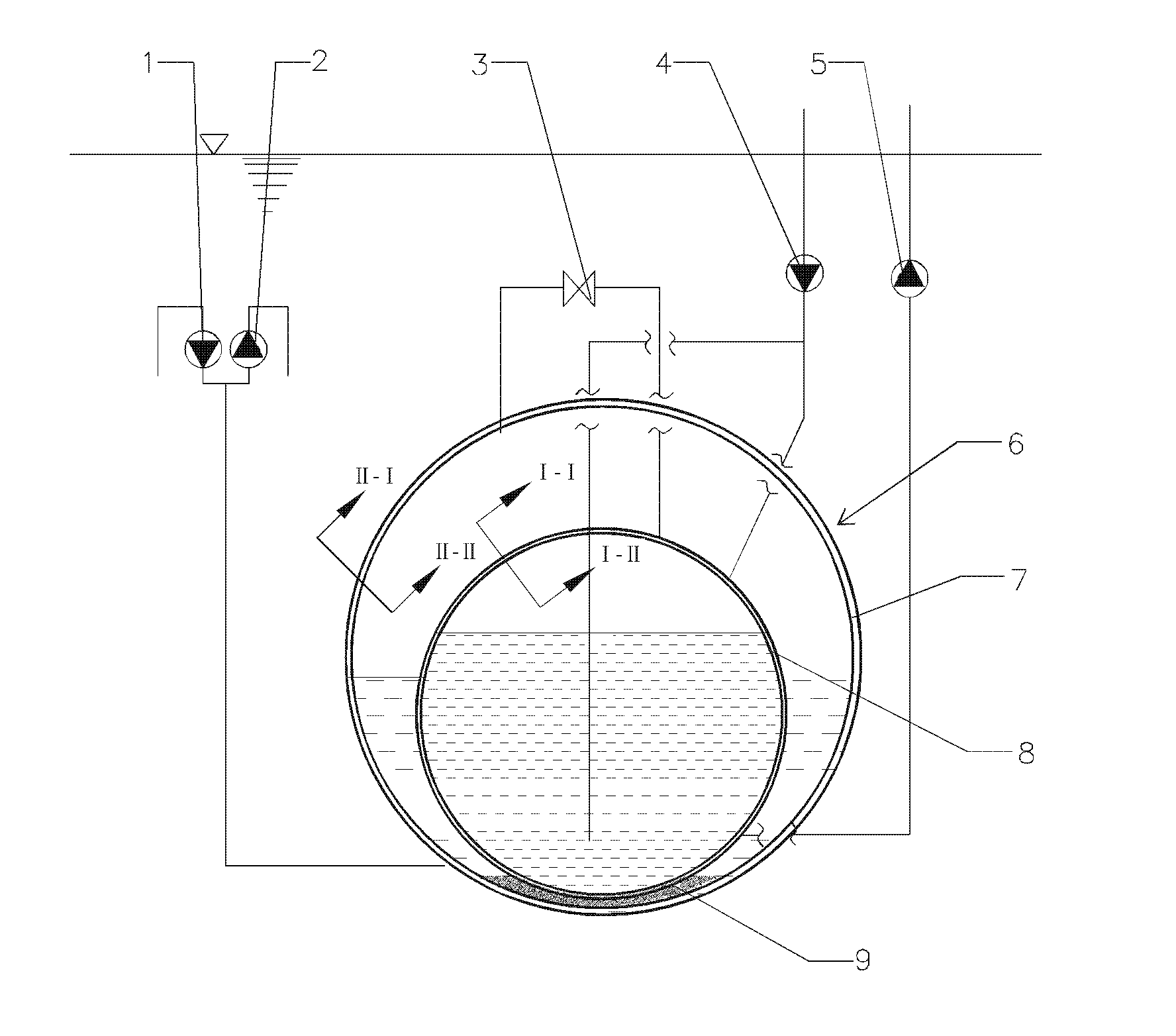
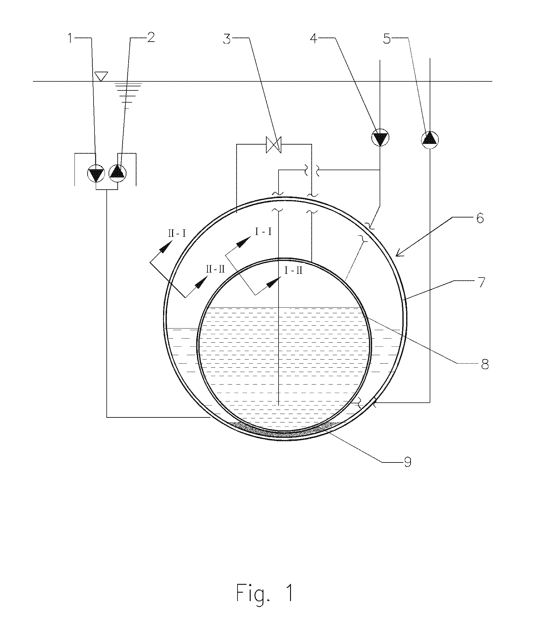
[0066]FIG. 1 illustrates a flow chart of a liquid storage, loading and offloading system...


PUM

PropertyMeasurementUnit
temperatureaaaaaaaaaa
pressureaaaaaaaaaa
pressureaaaaaaaaaa

Abstract

A liquid displacement system includes a storage tank, a volume of a first gas, and a volume of a second gas. The storage tank has at least one water ballast compartment to store water and at least one liquid storage compartment to store liquid and is configured symmetrically. A pump module may also be coupled to the storage tank. The pump module has at least one pair of loading pumps operating substantially at equal mass flow rate to displace the water with the liquid, and at least one pair of offloading pumps operating substantially at equal mass flow rate to displace the liquid with the water. Also, a gas valve module may be coupled to the storage tank to control pressure of the first gas and the second gas in the storage tank. The first gas is natural gas or inert gas. The second gas is natural gas.

Description

CROSS-REFERENCE TO RELATED APPLICATION(S)[0001]The present invention is a continuation in part of International Application PCT / CN2009 / 001008 filed on Sep. 7, 2009, now published in Chinese as WO / 2010 / 025625, which claims the benefit of CN200810196337.9 filed on Sep. 5, 2008, all of which are hereby incorporated by reference in their entireties.FIELD OF THE INVENTION[0002]The present invention relates to the field of a liquid displacement system. More particularly, the present invention relates to the field of an equal mass flow rate displacement system for utilizing the storage and transportation of hydrocarbon products and being applied with multifunctional offshore base, which can include oil / gas drilling wells, and production facilities of oil, natural gas, liquefied natural gas (“LNG”), liquefied petroleum gas (“LPG”), synthetic liquid hydrocarbon, or methanol.BACKGROUND OF THE INVENTION[0003]This section provides background information related to the present disclosure which i...

Claims


Application Information

Patent Timeline
Patent Type & Authority Patents(United States)
IPC IPC(8): E02D27/38
CPCF17C2270/0121F17C2221/033F17C2223/0161F17C2223/0153F17C2221/035B63B35/44Y10T137/0318
Inventor WU, ZHIRONG
Owner WU ZHIRONG
Why Eureka
Try Eureka