Medical connector with closeable luer connector

a technology of medical connectors and luer connectors, which is applied in the field of medical connectors with male luer connectors, to achieve the effect of reducing pressure and increasing the volume of the chamber

Active Publication Date: 2014-03-25
ICU MEDICAL INC
View PDF307 Cites 70 Cited by
  • Summary
  • Abstract
  • Description
  • Claims
  • Application Information

AI Technical Summary

Benefits of technology

[0011]When the separating force is removed, for example, by detaching the female connector from the first end of the housing, the resilient member once again can draw the housing and the valve member together. This causes the tip on the first end of the valve member to abut closely against a portion of the internal wall in a region near the first end of the male luer, and impedes fluid flow out of the valve.
[0016]A protrusion can project from the female portion (e.g., the end wall of the housing) and can be configured to extend into an opening formed in the bladder member. The protrusion can have an annular recess thereon configured to receive the annular wall forming the perimeter of the opening of the bladder member. The opening in the bladder member and the protrusion can be configured to form a generally liquid or gas tight seal between the protrusion and the bladder member so that the bladder member can be sealably supported by the protrusion and, hence, the end wall of the housing.
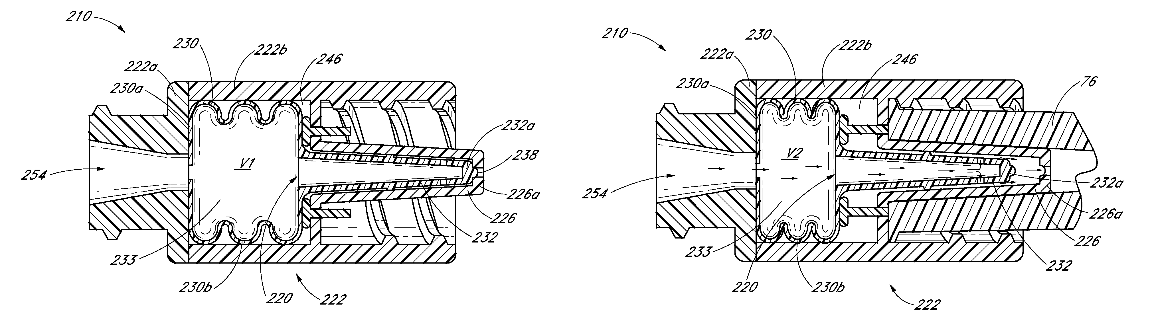
[0021]The diaphragm member can be positioned so as to exert a force on the valve member that biases the valve member toward the closed position. For example, without limitation, the diaphragm member can bias the tube member projecting from the valve base to sealably close against the inside surface of the luer tip. In some embodiments, the diaphragm member can be positioned within the luer connector so that, when the valve member is in the closed position, the diaphragm is partially deflected from its relaxed state so as to increase the bias force that the diaphragm exerts on the valve member.
[0022]The diaphragm member can form a partition within the housing so as to create a substantially fluid sealed cavity or chamber within the housing. The diaphragm member can be configured so that the volume within the cavity when the valve member is in the closed position is greater than volume within the cavity when the valve member is in the open position. In this configuration, the volume of space within the cavity can increase when the valve member moves from the open position to the closed position, thereby creating a force of suction that can reduce the amount of fluid or medicament that can flow through or drip out of an opening in the male luer tip as the valve member closes, by drawing such fluid back toward the cavity.
[0024]In some embodiments, the bladder member can have a generally cylindrical or tubular shape, and can be positioned within the housing so that the opening axially through the bladder member is generally coaxially aligned with an opening formed in a female connector portion of the housing and an opening formed in the male luer tip. The bladder member can have one end surface that can be sealably supported by or positioned against an end wall surface adjacent to the female connector portion of the housing. Similarly, a second end surface of the bladder member can be sealably supported by or positioned against a valve base of the valve member so as to define a chamber or cavity bounded generally by the tubular wall of the bladder member, the end wall of the housing, and the valve member. An opening formed through the end wall of the housing and an opening formed in the valve member can be in communication with the chamber. The volume within the chamber when the luer connector is in the closed position can be larger than the volume within the chamber when the luer connector is in the open position. The increase in the volume of the chamber as the valve member moves from the open to the closed position can create a reduced pressure that draws the fluid from the luer tip or tube back into or toward the chamber.
[0025]Some embodiments provide a method for selectively closing a medical connector, the method comprising supporting a resilient bladder member within a housing, moving a valve member at least partially supported within the housing between a connector open position and a connector closed position such that, in the closed position, the valve member substantially prevents liquid from flowing through the fluid passageway and, in the open position, the valve member permits liquid to pass through the fluid passageway, and moving the bladder member between a first configuration having a first volume in the connector closed position and a second configuration having a second volume in the connector open position. The second volume can be, but is not required to be, smaller than the first volume.

Problems solved by technology

It is often a challenge to keep such systems sterile and to prevent leakage of fluids when the various components are engaged and disengaged.

Method used


Image

  • Medical connector with closeable luer connector
  • Medical connector with closeable luer connector
  • Medical connector with closeable luer connector

Examples


Embodiment Construction

[0066]In some embodiments, the male luer includes closing mechanisms which function to prevent and / or impede fluid from escaping from or entering into the male luer, while allowing fluid flow when the male luer is manually opened or engaged with a corresponding female luer. As used herein, terms such as “closed” or “sealed” should be understood as obstructions or barriers to fluid flow. These terms should not be understood to require that a particular structure or configuration achieves a complete fluid closure in all circumstances.

[0067]Some medications, including those used during chemotherapy, can be harmful to a patient in certain applications. For example, exposure to the skin can sometimes result in a chemical burn. Inhalation of aerosolized forms of some medications also can be harmful. Thus, control over the containment of the medication is highly desirable.

[0068]At present, some potentially harmful medications are distributed in sealed vials. The medication can be removed f...


PUM


Abstract

Some embodiments disclosed herein relate to a medical connector having a selectively closable male end portion. Embodiments are configured to open upon connection with a female connector or female tipped medical implement. Some embodiments include an internal cavity configured to change size as the connector moves from the open to closed or closed to open positions. In some embodiments, the connector is configured to draw fluid from the male end toward the other end of the connector as the connector closes.

Description

PRIORITY CLAIM AND INCORPORATION BY REFERENCE[0001]The present application claims the benefit of U.S. Provisional Patent Application No. 61 / 139,514, filed Dec. 19, 2008 (entitled “MEDICAL CONNECTOR WITH CLOSEABLE LUER CONNECTOR”).[0002]The present application hereby incorporates by reference the entire disclosure of U.S. Provisional Patent Application No. 61 / 139,514, filed Dec. 19, 2008 (entitled “MEDICAL CONNECTOR WITH CLOSEABLE LUER CONNECTOR”) and U.S. Pat. No. 5,685,866, issued Nov. 11, 1997 (entitled “MEDICAL VALVE AND METHOD OF USE”) as if fully set forth herein.BACKGROUND OF THE INVENTION[0003]1. Field of the Invention[0004]Embodiments relate generally to medical connectors through which fluids flow, and in particular, to medical connectors with male luers.[0005]2. Description of the Related Art[0006]Systems of connectors, valves, and tubing are routinely used in hospitals and other medical settings for facilitating the transfer of fluids to and from patients. It is often a c...

Claims


Application Information

Patent Timeline
Patent Type & Authority Patents(United States)
IPC IPC(8): A61M39/00
CPCA61M2039/268A61M2039/267A61M39/26
Inventor ANDERSON, HAROLDLOPEZ, CHRISTOPHERFANGROW, JR., THOMAS F.
Owner ICU MEDICAL INC
Why Eureka
Try Eureka