
Maintenance method of radiological image detection apparatus

a radiological image and detection apparatus technology, applied in calibration apparatus, radiation measurement, instruments, etc., can solve the problems of scintillator deterioration, loss of moisture resistance, attenuation of radiation entering the scintillator, etc., to achieve the effect of properly and easily detecting the deterioration of the phosphor

Inactive Publication Date: 2014-03-25
FUJIFILM CORP
View PDF18 Cites 1 Cited by
  • Summary
  • Abstract
  • Description
  • Claims
  • Application Information

AI Technical Summary

Benefits of technology

The technical effect of this patent is to provide a method for detecting the deterioration of a phosphor in a simple and effective way. This can help to prolong the life of the phosphor and improve its performance in various applications.

Problems solved by technology

This causes a concern of attenuation of the radiation entering the scintillator.
However, if the substrate is peeled off, the moisture resistance which is attained by the substrate is lost.
Since CsI which is the material of the scintillator exhibits deliquescence, the scintillator may deteriorate due to the moisture permeation.
On the other hand, if the substrate is peeled off, the moisture permeation occurs over the entire area of the scintillator and the scintillator may deteriorate from its central portion.
Therefore, it is difficult for NPS evaluation to detect deterioration of a scintillator properly.
As such, extraction of only a structure noise component is difficult.

Method used


Image

  • Maintenance method of radiological image detection apparatus
  • Maintenance method of radiological image detection apparatus
  • Maintenance method of radiological image detection apparatus

Examples


Embodiment Construction

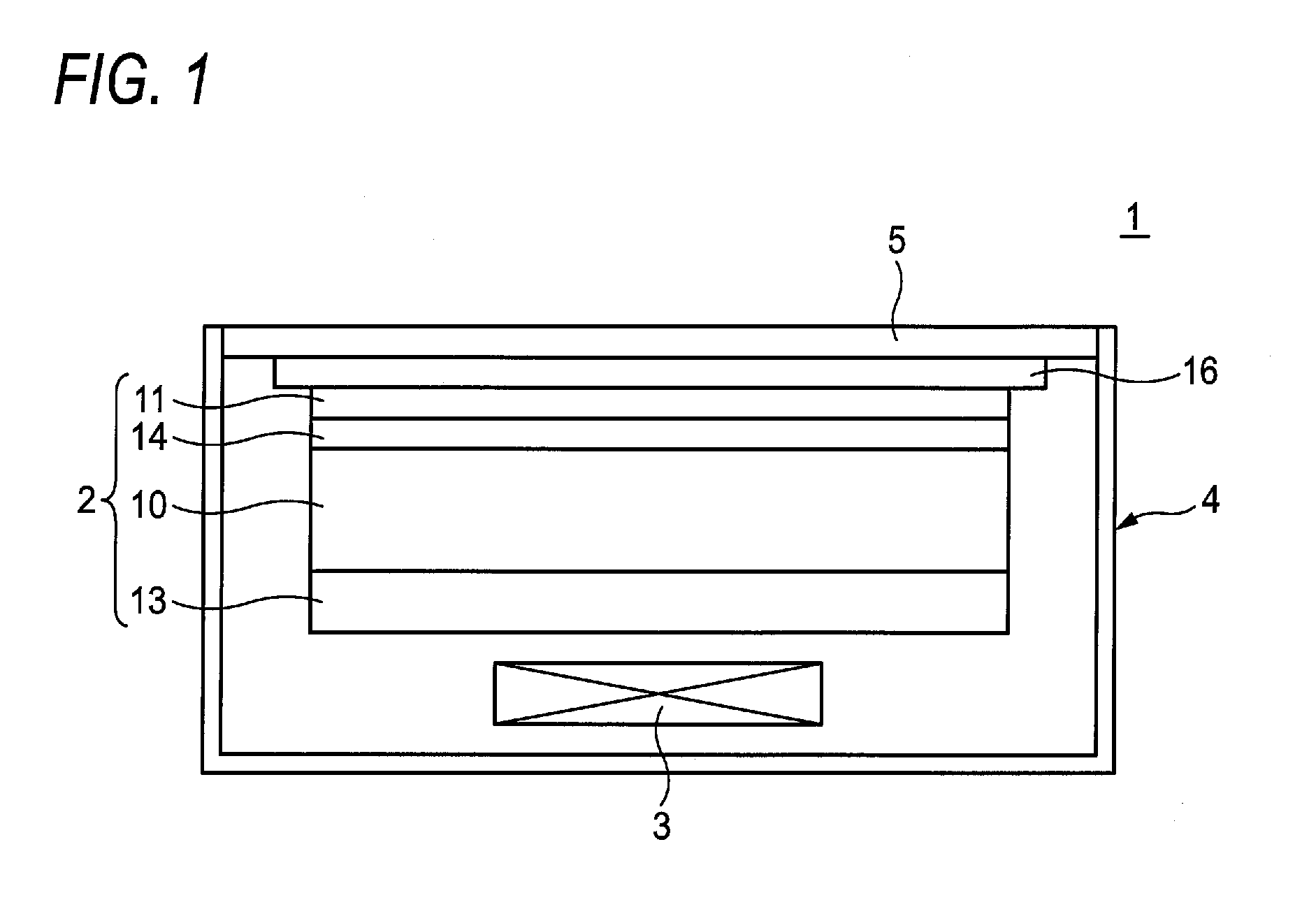
[0028]FIG. 1 shows the configuration of an example radiological image detection apparatus to be used for describing maintenance methods according to embodiments of the present invention.

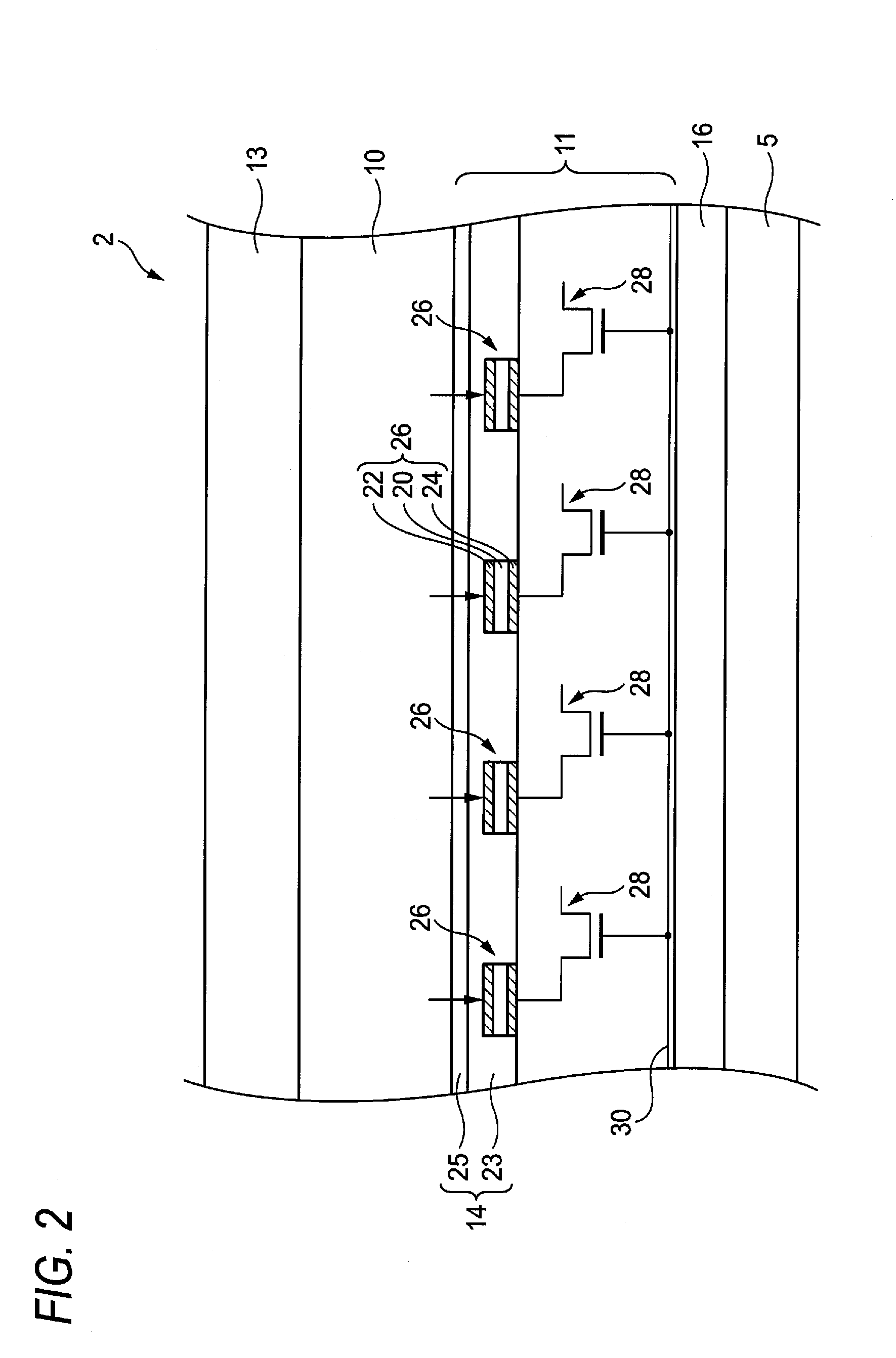
[0029]The radiological image detection apparatus 1 shown in FIG. 1 is a portable radiological image detection apparatus (hereinafter referred to as a cassette). The cassette 1 is equipped with a detection portion 2 for detecting radiation, a control portion 3 for controlling the operation of the detection portion 2 and generating a radiation image on the basis of the radiation detected by the detection portion 2, and a housing 4 which houses the detection portion 2 and the control portion 3.

[0030]In the housing 4, a subject (e.g., a shooting subject part of a patient) is placed on a top plate 5 which overlaps with the detection portion 2. Radiation coming from the subject passes through the top plate 5 and entering the detection portion 2. The top plate 5 is made of a material which is low in radiati...


PUM


Abstract

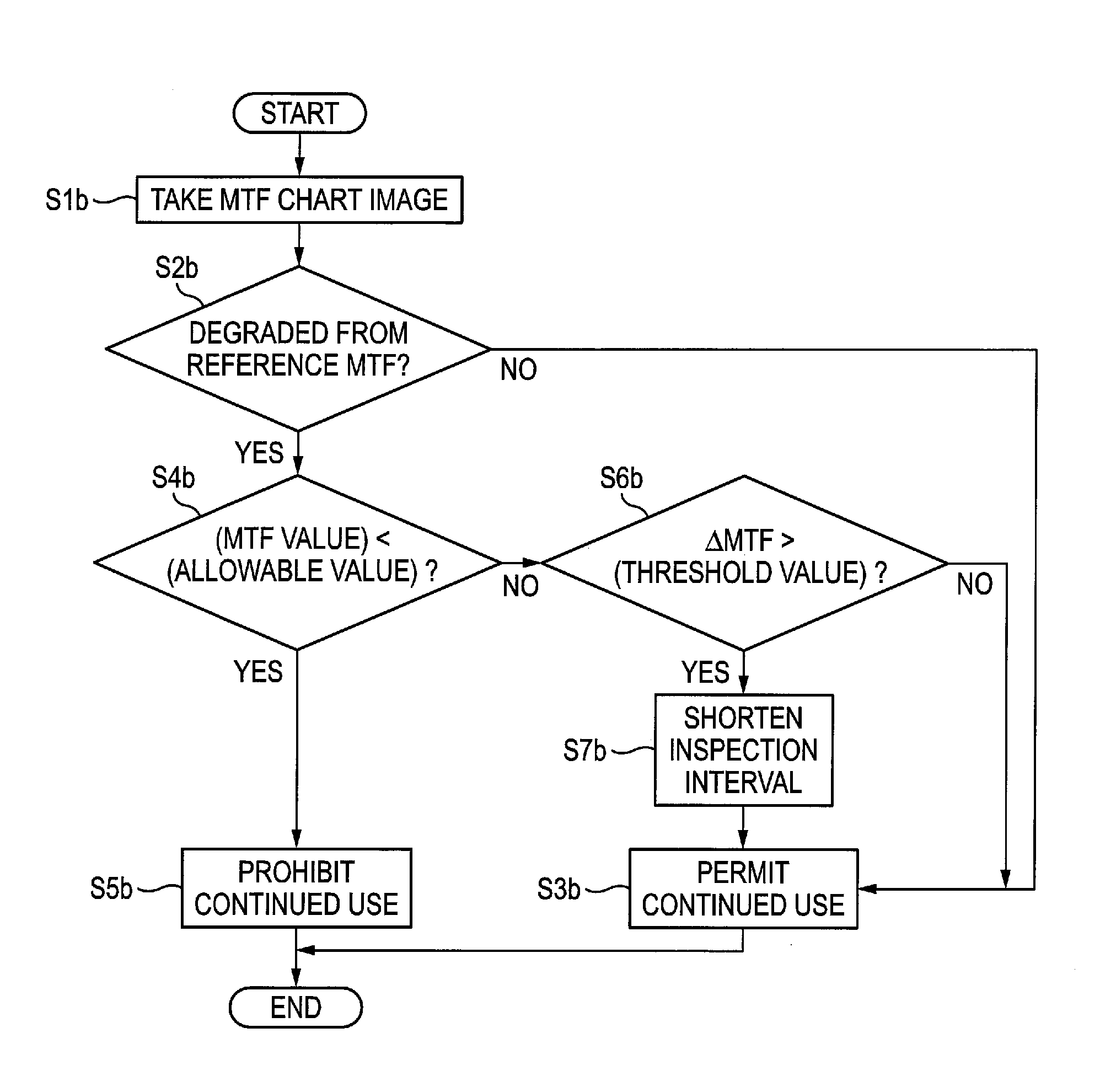
An maintenance method of a radiological image detection apparatus including: a phosphor containing a fluorescent material which emits fluorescent light when exposed to radiation and a thin-film type sensor portion which is disposed adjacent to the phosphor on a radiation incidence side and supported by the phosphor and detects fluorescent light generated in the phosphor, the maintenance method includes: regularly performing at least one of a structural noise inspection, an MTF inspection and a dark current inspection, to detect deterioration of the phosphor.

Description

CROSS-REFERENCE TO RELATED APPLICATIONS[0001]This application is based on and claims priority under 35 USC 119 from Japanese Patent Application No. 2011-051773 filed on Mar. 9, 2011; the entire content of which is incorporated herein by reference.BACKGROUND[0002]1. Technical Field[0003]The present invention relates to a maintenance method of a radiological image detection apparatus.[0004]2. Related Art[0005]In recent years, radiological image detection apparatuses employing an FPD (Flat Panel Detector) for detecting a radiation image and generating digital image data are utilized in practice, and spreading rapidly because the image can be checked immediately in comparison with the case of a conventional imaging plate. Such radiological image detection apparatuses of various types are proposed. An example of this is an indirect conversion type.[0006]A radiological image detection apparatus of indirect conversion type has: a scintillator formed from fluorescent material such as CsI (c...

Claims


Application Information

Patent Timeline
Patent Type & Authority Patents(United States)
IPC IPC(8): G01D18/00
CPCG01T7/005
Inventor IWAKIRI, NAOTONAKATSUGAWA, HARUYASU
Owner FUJIFILM CORP
Learn More