Recording apparatus

a recording apparatus and jet technology, applied in electrographic processes, instruments, transportation and packaging, etc., can solve problems such as troublesome printed images and malfunctions of recording heads, and achieve the effect of detecting the deterioration of insulation

Inactive Publication Date: 2005-02-22
CANON KK
View PDF8 Cites 4 Cited by
  • Summary
  • Abstract
  • Description
  • Claims
  • Application Information

AI Technical Summary

Benefits of technology

To solve the above-mentioned problem, an object of the present invention is to provide a recording apparatus capable of detecting the deterioration of the insulation by knowing whether there is the leakage current from the surface of a conveyer belt to avoid the damage of the recording head beforehand.

Problems solved by technology

On the other hand, the ink head recording head is not always constituted by materials resistant to a high voltage but may generally be often weak to the static electricity or a high voltage.
Thus, since the high voltage is always applied to the conveyor belt, there may be a leakage current between the electro-conductive section of the conveyor belt and the ink jet recording head if the insulation layer of the conveyer belt is damaged during the use due to a wear or a fatigue, resulting in the malfunction of the recording head.
Further, when the conveyor belt having a defect such as a pin hole is continuously used as it is, the damage of the recording head becomes larger to cause the trouble in the printed image.

Method used


Image

  • Recording apparatus
  • Recording apparatus
  • Recording apparatus

Examples


first embodiment

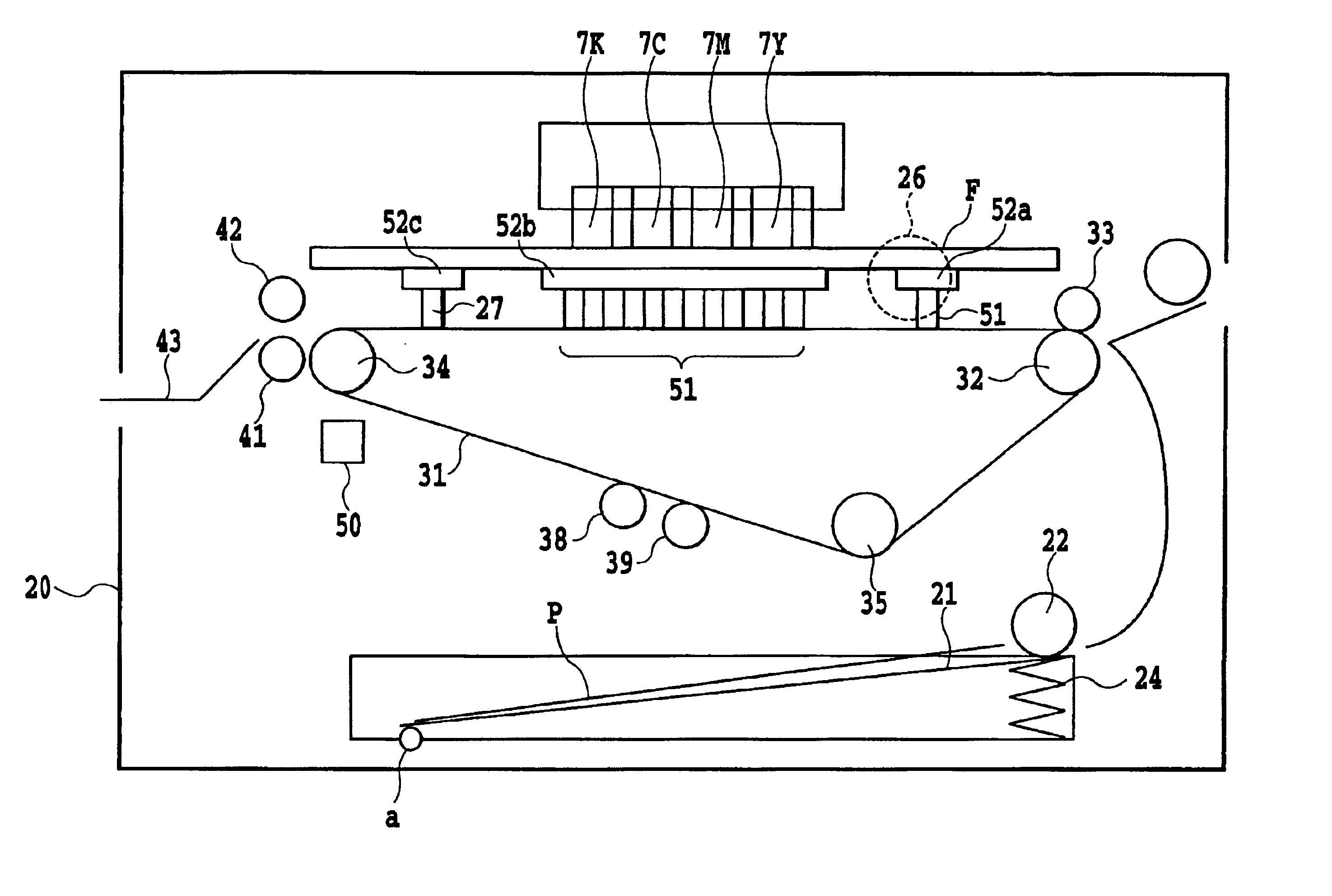
FIG. 4 illustrates a cross-section of the entirety of a recording apparatus according to the present invention, including a sheet feeding section, a conveyor section, a recording head section and a sheet delivery section described hereinafter.

In the sheet feeding section, a presser plate 21 on which recording sheets P are laid and a feed roller 22 for feeding sheets P are provided. The recording sheet P is biased by a presser plate spring 24 to the feed roller 22 rotatable about a rotary shaft coupled to a base 20. In this state, the recording is carried out on the recording sheet P while the feed roller 22 is rotating. A separation pad not shown having a high frictional coefficient for avoiding the double feed of the recording sheets P and a separation nib not shown for separating the recording sheet are provided in the presser plate 21. Also, a release cam not shown is provided for releasing the contact of the presser plate 21 with the feed roller 22.

According to the above-mention...

second embodiment

In the first embodiment, a method is disclosed, for stopping the operation of the apparatus at a time when the leakage is detected. Contrarily, in the second embodiment, another method is disclosed, in which even if the leakage is detected in either one group of the electrode plates, the printing is continued as it is.

FIG. 12 illustrates an operational flow chart of the control section in the second embodiment.

Upon starting the printing operation (step 1), the conveyor belt motor is first driven.

The high voltage is applied to the conveyor belt when the speed of the conveyor belt becomes constant, and when the attracting force necessary for conveying the recording sheet has been obtained, the recording sheet is conveyed to start the printing operation (step 2).

The control section always carries out the detection of the leakage if any until the printing operation is finished. If the leakage is detected in the voltage charging section of +3.0 kV (step 3), the application of the high vo...


PUM


Abstract

To provide a recording apparatus capable of detecting the deterioration of insulation to prevent the damage of a recording head by detecting whether or not there is the current leakage from a surface of a conveyor belt. The inventive recording apparatus includes a conveyor belt for conveying a recording medium comprising a plurality of inner electro-conductive members, a charging section for charging the inner electro-conductive members by a high voltage to attract the recording medium onto the conveyor belt by an electro-static force, a recording head for carrying out the recording on the recording medium attracted onto the conveyor belt, a leakage detection roller for detecting the deterioration of the insulation of the conveyor belt, and a control section for treating the abnormality in accordance with the results detected by the leakage detection roller.

Description

This application claims priority from Japanese Patent Application No. 2002-251988 filed Aug. 29, 2002, which is incorporated hereinto by reference.BACKGROUND OF THE INVENTION1. Field of the InventionThe present invention relates to an ink jet recording apparatus, particularly, to a conveying device for the ink jet recording apparatus.2. Description of the Related ArtThere is a type using a recording head of a full-line type in an ink jet recording apparatus, which is capable of recording a high-quality image at a high speed. In this recording apparatus, a method has generally been known in which an electro-static force is generated in a conveyor belt by applying electric charge thereto from electro-conductive electrodes provided in the conveyor belt to attract a conveyed article.The above-mentioned conveyor device will be described with reference to FIGS. 1 to 3.As shown in FIG. 1, the conveyor belt is formed of electrode plates 36a, 36b made of electro-conductive metal, a base laye...

Claims


Application Information

Patent Timeline
Patent Type & Authority Patents(United States)
IPC IPC(8): G03G15/16B65H5/00B41J2/01
CPCG03G15/166
Inventor CHINO, NORIYUKIKANOME, OSAMU
Owner CANON KK
Why Eureka
Try Eureka