Device, cooling function monitoring apparatus, and fan deterioration monitoring program storing medium

a technology for monitoring apparatus and fan, which is applied in the direction of lighting and heating apparatus, process and machine control, instruments, etc., can solve the problems of dust or dirt attaching around the fan, not achieving sufficient air cooling, and insufficient air cooling

Inactive Publication Date: 2007-09-20
FUJITSU LTD
View PDF5 Cites 4 Cited by
  • Summary
  • Abstract
  • Description
  • Claims
  • Application Information

AI Technical Summary

Benefits of technology

[0045]According to the present invention, deterioration of an air-cooling capability of a fan can be correctly detected. In particular, for a device which uses a heat-generating part the operating rate of which changes depending on a temperature, deterioration detection is correct.

Problems solved by technology

Since the fan also consumes electric power, the fan approaches the end of its lifetime with its rotation.
That is, although sufficient air-cooling can be obtained in a new device, when the device is aged, sufficient air-cooling cannot be obtained by rotation of the fan.
That is, dust or dirt gradually attaches around the fan while the device is being used, a sufficient air flow is not generated even though the fan is rotated at a predetermined rotating speed, and sufficient air cooling cannot be achieved.
Dust or dirt attaches around a fan not to achieve sufficient air-cooling.
As a result, when the throttling is performed, since the fan is rotated, the CPU operates the device at a low processing speed of the CPU without detecting that the low processing speed is caused by the dust or dirt.
An increase in temperature when a heat-generating part such as a CPU operates is caused by not only deterioration of a fan but also an influence of an environmental temperature of a device in which the heat-generating part is mounted at that time.
Therefore, in the proposition of Japanese Patent Application Laid-open No. 3-203395 in which an ambient temperature is measured to detect deterioration of the fan, deterioration of the fan cannot be correctly detected.
Even though dust or dirt attaches around the fan to deteriorate cooling capacity, deterioration (deterioration of air-flow generating capability) of the fan cannot be detected when the rotating speed of the fan is normal.

Method used


Image

  • Device, cooling function monitoring apparatus, and fan deterioration monitoring program storing medium
  • Device, cooling function monitoring apparatus, and fan deterioration monitoring program storing medium
  • Device, cooling function monitoring apparatus, and fan deterioration monitoring program storing medium

Examples


Embodiment Construction

[0053]An embodiment of the present invention will be described below.

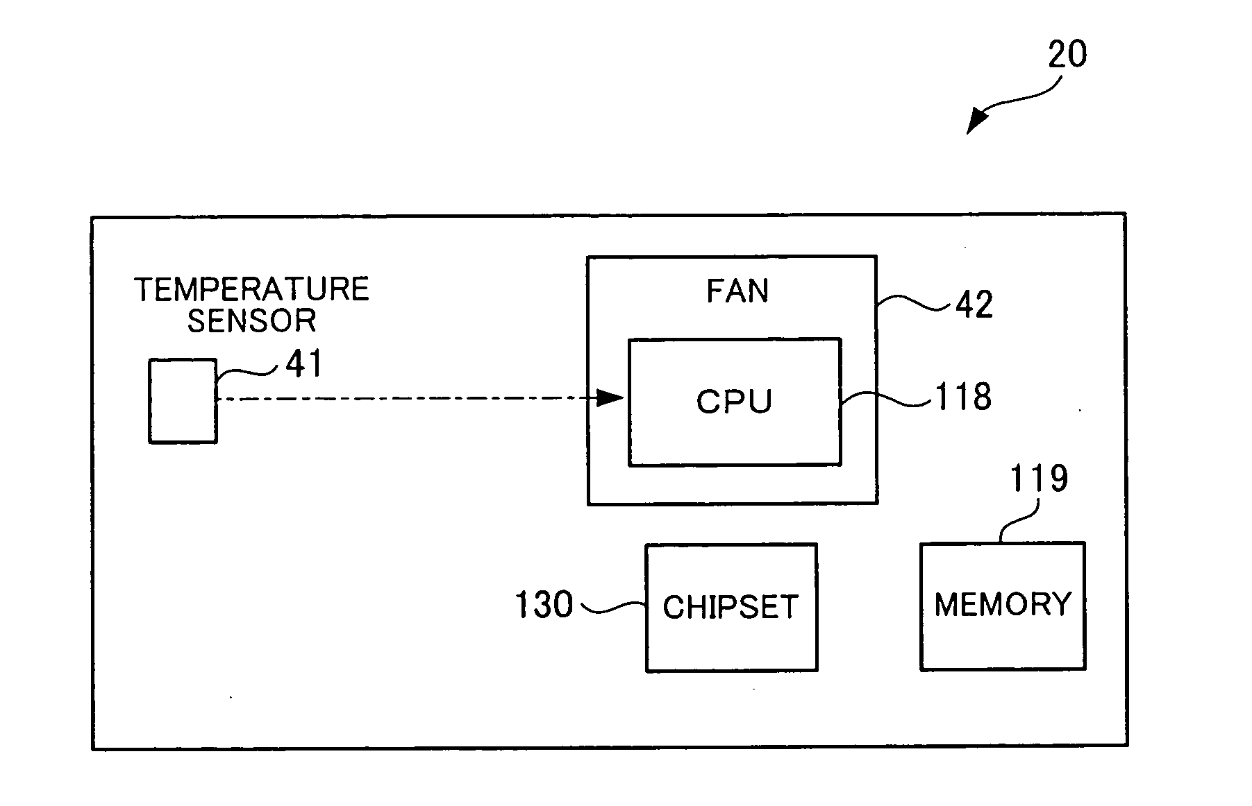
[0054]FIG. 3 is an external perspective view of a notebook personal computer (to be referred to as a “notebook PC” hereinafter) serving as an embodiment of a device according to the present invention.

[0055]The notebook PC 10 includes a main-body unit 20 and a display unit 30. The main-body unit 20 and the display unit 30 are connected by a connecting unit 40 such that the display unit 30 is openable / closable with respect to the main-body unit 20 in a direction of an arrow A-A. In FIG. 1 shows a notebook PC in a state in which the display unit 30 is opened with respect to the main-body unit 20.

[0056]In the main-body unit 20, on the upper surface, a keyboard 21, a track pad 22, a left-click button 23, a right-click button 24, and an engagement unit 25 which engages the display unit 30 when the display unit 30 is closed. On side surfaces of the main-body unit 20, a side surface 26 of an optical disk drive on which an ...


PUM


Abstract

A relationship between an operating rate and a temperature of a metal part when a fan is in a normal state is stored in advance, a temperature of a heat-generating part and a temperature of a reference point are actually measured in an operation to designate a temperature of the heat-generating part, and it is determined that a cooling capability deterioration state is set when the actually measured temperature of the heat-generating part is higher than an estimated temperature by a predetermined threshold value or higher.

Description

BACKGROUND OF THE INVENTION[0001]1. Field of the Invention[0002]The present invention relates to a device having a heat-generating part which generates heat in operation and a fan which generates an air flow to air-cool the heat-generating part, a cooling function monitoring apparatus which monitors a cooling function of the fan, and a fan deterioration monitoring program storing medium in which a fan deterioration monitoring program for giving a function of monitoring deterioration of the fan to the device is stored.[0003]2. Description of the Related Art[0004]In a conventional art, when a heat-generating part which generates heat in operation must be mounted in a device, an arrangement position of the heat-generating part in the device is schemed, or, if the cooling is not satisfied by scheming the arrangement position, the heat-generating part is cooled by an air flow generated around the heat-generating part.[0005]For example, in a personal computer, heat generation from an LSI ...

Claims


Application Information

Patent Timeline
Patent Type & Authority Applications(United States)
IPC IPC(8): H01L23/467G05D23/00
CPCG06F1/206H05K7/20
Inventor URITA, KENJI
Owner FUJITSU LTD
Why Eureka
Try Eureka